![<?echo $_SERVER['SERVER_NAME'];?>](/template/twentyseventeen/skin/images/header.jpg)
For high-power built-in/external lamp power supplies above 25W, due to high power factor and THD requirements, and the output current is relatively large, the current solution is usually a two-stage rack (APFC+DC/DC). Mainly.
The traditional two-stage solution, because it requires two chips to be controlled separately, is often difficult to optimize in terms of chip power supply, drive efficiency and volume, BOM quantity and cost.
As a solution for Jingfeng Mingyuan in high-power high-end lamp driving power supply, UR3311 is a two-in-one control chip based on two-stage architecture, which can be applied to BOOST+FLYBACK isolation application or BOOST+BUCK. Non-isolated applications. Suitable for lamp power supplies with high power factor, low THD, low output current ripple requirements.
Chip Features UR3311
1, patented smart chip power supply
Patented smart chip power supply and critical current valley detection without auxiliary winding
UR3311 is the simplest and lowest cost solution for transformer and inductor design in the current two-stage solution. The power inductor of the front stage BOOST is a single winding inductor, the rear stage isolation FLYBACK is a double winding transformer, and the rear stage non-isolated BUCK is a single winding inductor.
2, simpler BOOST inductance design
Maintain full voltage to maintain high efficiency.
When the BOOST stage is the low-voltage input, the latched BOOST output voltage is 280V. When the input voltage rises, the BOOST output voltage is follow-type, which realizes a simpler BOOST inductor design and maintains full voltage to maintain high efficiency.
3, the best conversion efficiency
Critical Current Mode (BCM) + Valley Quasi-Resonant Mode
Both stages are critical current mode (BCM) + valley quasi-resonant mode of operation for optimum conversion efficiency. High precision constant current algorithm and perfect protection function.
Characteristic advantage UR3311
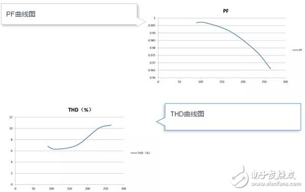
Full voltage range PF" 0.95, THD "10%;
Output current ripple is less than ±5%, no stroboscopic;
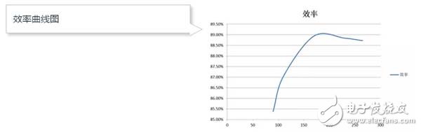
Up to 88% efficiency (isolation);
"500ms quick start;
Excellent linearity and load regulation, good consistency;
Patented algorithms that greatly reduce the number of peripheral devices;
Support for isolated and non-isolated applications;
Built-in comprehensive protection features;
Typical application UR3311
Full voltage input high PF low frequency flash external power supply application input voltage: 90~270Vac
Output LED: 36V/1A
PF"0.95
THD "15% 1
PCB physical map

Schematic

PF, THD and efficiency graph
UR3311 You can select the BOOST+FLYBACK and BOOST+BUCK topologies as needed. You only need to change the connection of the MODE pin to select different application topologies. In general, external power supplies for panel lights or other applications should use the BOOST+FLYBACK topology. This topology has the advantages of high security level and good consistency. BOOST+BUCK topology can be used for high efficiency, high efficacy built-in or second-class lighting applications. This topology has the advantages of high efficiency and low application cost.
24 hours mechanical Timer
Instant indicator
Min.setting time:15 minutes. Max.setting timer:24 hours
With hand switch,can be switched to operating and
setting at any time
Instructions:

1. Set program: 1 pin is equivalent to 15 minutes. Determine desired start time and push down pins until desired
off time.
For instance, if you want electrical devices to work from 8:00am to 11:00am and from 13:00pm to 17:00pm, you
just need to put down allthe pins between the three period time.
2. Set the current time: Turning the dial clockwise until the arrow pointing to
current time.
For example,if now it is 8:00 am, please turn the dial and make sure the
arrow point to 8. (See the picture.)
3. Plug the electrical device directly into the timer. Make sure the electrical
device is power-on.
4. Plug the timer into electrical outlet and the electrical device will be work
according to the setting program.
Note: = Normal Ope n = Timing
Make sure the switch on the Timing position. If it
is on the [Normal Open" mode, the electrical device is
always power-on and the timer function no work.
Specifications:
|
Rated Voltage, Current and Power |
As shown on the label |
|
Time Setting Range |
15minutes24hours |
|
Working Temperature |
-10℃?+55℃ |
|
Operation |
Clockwise |
|
Insulation Resistance |
>100M |
|
Inherent Loss |
≤1W |
Application:
1. To enable high-power electric appliances to run automatically at off-peak time if there is different electricity
price according to different periods of time in some areas.
2. To use for electric appliances which need time control, such as water heaters, air conditioners, drinking
fountains, rice cookers, advertising lights and so on.
3. To control the charging time. For example, battery of electric bikes or mobile phones, storage batteries, etc.
4. Occasions which need switch on/off frequently, like interval spray irrigation for flowersand lawn, cyclical
adding oxygen to fish jar, fountains and so on.
5. Home safety precautions and lighting.
Caution:
1.D o not exceed the maximum ratings of the timer.
2.M ust reset the current time after power failure.
3.D o not plug the timer directly into the working electrical appliances.
4.U nless changing the setting, keep the program same every day.
5.D o not disassemble timer by yourself. Professionals service are needed for maintenance.
6.T his item is only for indoor use.
Mechanical Timer, mechanical timer socket, 24hr mechanical timer, mechanical timer plug, mechanical timer adaptor
NINGBO COWELL ELECTRONICS & TECHNOLOGY CO., LTD , https://www.cowellsocket.com