![<?echo $_SERVER['SERVER_NAME'];?>](/template/twentyseventeen/skin/images/header.jpg)
The drive circuit (Drive Circuit), located between the main circuit and the control circuit, is an intermediate circuit used to amplify the signal of the control circuit (that is, amplifying the signal of the control circuit to enable it to drive the power transistor), called the drive circuit.
Drive circuit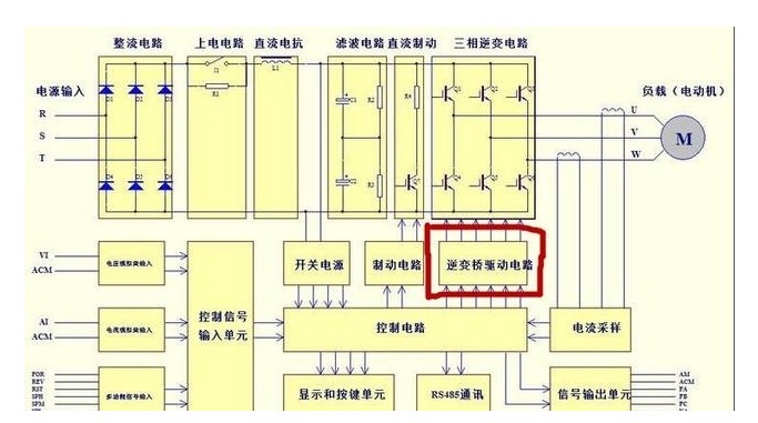
The 6-channel pulse signal output by the control circuit enters the drive circuit (marked in red). After the isolation and power amplification of the optocoupler, the IGBT is driven to achieve our control switching effect and invert the DC into the three-phase AC we need. Voltage
Analysis of three common inverter drive circuits(1) Introduction of HCPL-316J chip. HCPL-316J is a photoelectric coupling driver, which has the same function as A316J and can be interchanged. The internal structure and pin functions of HCPL-316J are shown in Figure 5-18.

Figure 5-18 HCPL-316J internal structure and pin functions
The output current of HCPL-316J can reach 2A, and it can directly drive IGBT. Its internal circuit is divided into input circuit and output circuit by photocoupler. It uses digital circuit with high input impedance as signal input terminal, no need for large input Signal current; HCPL-316J has internal under-voltage lockout and IGBT protection circuits. When the power supply voltage of the chip output circuit is lower than 12V, the under-voltage protection circuit will act. The internal transistor between pins 12 and 11 is cut off, and pin 11 stops from 11 The pin outputs a drive signal with insufficient amplitude. In addition, when the IGBT has an overcurrent, the overcurrent detection circuit on the periphery of the chip increases the voltage of pin 14 and the internal protection circuit operates. On the one hand, the MOS tube is turned on and the output drive from pin 11 is stopped. In addition to the signal, on the other hand, the output signal is amplified and sent to the fault detection circuit (FAULT) by the photocoupler. In addition to blocking the input circuit, this circuit will also output a low level from pin 6 to the CPU or related circuits. If the IGBT has an over-current fault, to release the input blockade, a low-level reset signal must be input to pin 5.
The input and output relationship of HCPL-316J key pins is shown in the table
Table 5-3 HCPL-316J key pin input and output relationship
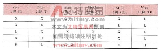
Note X: high level or low level; H: high level; L: low level; I: input; O: output.
(2) Analysis of the drive circuit composed of HCPL-316J. Figure 5-19 is a U-phase drive circuit composed of HCPL-316J, which is used to drive the U-phase upper and lower arm IGBTs. The circuit also has IGBT overcurrent detection and protection functions.
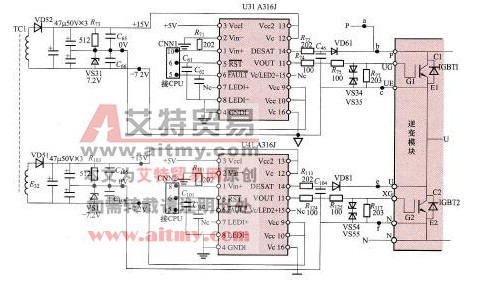
Figure 5-19 U-phase drive circuit composed of HCPL-316J
1) The working principle of the drive circuit. The induced electromotive force on the secondary winding of the switching transformer TC1 is charged to the capacitor by the rectifier diode VD52 to obtain a voltage of 22.2V. The voltage is divided into 15V and 7.2V by R73 and VS31. With the connection point of R73 and VS31 being 0V, the upper end voltage of R73 is + 15V, VS31 lower end voltage is -7.2V, +15V is sent to U31 (A316J) 13 and 12 pins as the power supply and positive voltage of the output circuit, -7.2V voltage is sent to U31 9 and 10 pins as the negative voltage of the output circuit . When the inverter is working normally, the CPU will send a U+ phase pulse to pin 1 of U31. When the pulse is high level, the Darlington tube (composite triode) inside pins 12 and 11 of U31 is turned on, and the voltage is +15V. → U31 pin 12 → U31 internal transistor → U31 pin 11 → R75 → G pole of the upper side IGBT, the E pole of the IGBT is connected to the negative pole of VS31, and the voltage of the E pole is 0V, so the UGE voltage of the upper side IGBT is positive When the U+ pulse low level is sent to pin 1 of U31, the internal MOS tubes of pins 11 and 9 of U31 are turned on, -7.2V voltage → pin 9 of U31 → internal MOS tube → pin 11 of U31 →R75→G pole of the upper-side IGBT, the E-pole of the IGBT is connected to the negative electrode of VS31, and the voltage of the E-pole is 0V, so the upper-side IGBT is cut off because the UGE voltage is negative.
The working principle of the lower bridge arm drive circuit is the same as that of the upper bridge arm, so it will not be described here.
2) Protection circuit. R72, C46, ​​VD61 and U31 (A316J) internal IGBT over-current detection and protection circuit, etc. constitute the upper-side IGBT over-current protection circuit.
When the upper-side IGBT is normally turned on, the conduction voltage drop between the C and E poles is generally below 3V, the voltage of the negative pole of VD61 is low, the voltage of pin 14 of U31 is pulled down, and the IGBT detection and protection circuit inside U31 does not work. If an overcurrent occurs between the C and E poles of the IGBT, the conduction voltage drop between the C and E poles will increase, the negative voltage of VD61 will increase, and the voltage of pin 14 of U31 will be increased. If the overcurrent causes the IGBT to conduct voltage When the voltage drops to more than 7V, the voltage on pin 14 of U31 is raised a lot, and the internal IGBT detection and protection circuit of U31 operates. On the one hand, it controls U31 to stop outputting driving signals from pin 11, and on the other hand, it makes U31 output low level from pin 6 to the CPU , Inform that the IGBT has over-current, and cut off the U31 internal input circuit at the same time. After the overcurrent phenomenon is eliminated, input a low-level signal to pin 5 of U31 to reset the internal circuit, and U31 restarts work.
R77 is used to release the charge on the gate capacitance of the IGBT and improve the switching speed of the IGBT. VS34 and VS35 are used to suppress the large interference signals that enter the gate of the IGBT.
For the 22kV Oil Immersed Power Transformer, we can produce capacity upto 420MVA. We use the best quality of raw material and advance design software to provide low noise, low losses, low partial discharge and high short-circuit impedance for power transformer.
Our power transformer are widely used in national grid, city grid, rural grid, power plant, industrial and mining enterprise, and petrochemical industry.
220Kv Transformer,220Kv Power Transformer,High Quality Power Transformer,Oil Immersed Transformer
Hangzhou Qiantang River Electric Group Co., Ltd.(QRE) , https://www.qretransformer.com