![<?echo $_SERVER['SERVER_NAME'];?>](/template/twentyseventeen/skin/images/header.jpg)
The oscillating current is a current whose magnitude and direction change with the period. The circuit that can generate the oscillating current is called an oscillating circuit. The simplest oscillating circuit is called the LC loop.
The oscillating current is an alternating current, which is a high-frequency alternating current. It cannot be generated by the rotation of a coil in a magnetic field and can only be generated by an oscillating circuit.
The condition of the oscillating circuit physical model (ie, the ideal oscillating circuit)
1 The resistance of the whole circuit is R=0 (including coils and wires). From the energy point of view, there is no other form of inward energy conversion, that is, the heat loss is zero.
2 Inductor coil L concentrates the inductance of all circuits, capacitor C concentrates the capacitance of all circuits, and no submerged capacitor exists.
The 3LC oscillating circuit does not radiate electromagnetic waves to the external space when electromagnetic oscillation occurs. It is a closed circuit in a strict sense. Only the mutual conversion between the magnetic field energy of the coil and the electric field energy of the capacitor occurs inside the LC circuit, even if the electric field generated in the capacitor changes, The varying magnetic field generated in the coil also does not excite the corresponding magnetic field and electric field according to Maxwell's electromagnetic field theory, and radiates electromagnetic waves to the surrounding space.
1. PLC oscillation circuit ladder diagram and output waveform diagram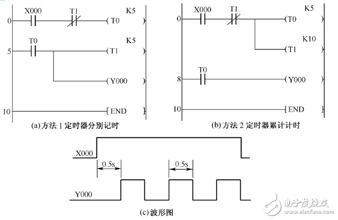
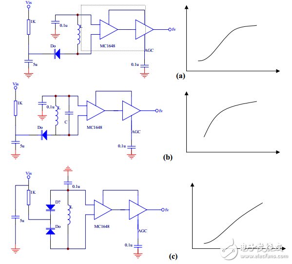
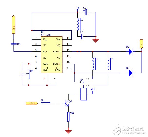
It is a monolithically integrated emitter-coupled oscillator that outputs MECL levels. When the circuit is working, the parallel resonant circuit of the external inductor L and the capacitor C can form a fixed frequency oscillator. If an external varactor is connected, the DC bias of the varactor can be controlled to form an LC voltage controlled oscillator. The MC1648 operates at 5V or 5.2V. The maximum working frequency can reach 225MHz. Several common varactor connection methods and corresponding voltage control characteristics are shown in the following figure. (a)(b) is a single pipe connection, and the control voltage is applied to the varactor. flow. (c) Double-tube back-to-back connection, which has high operating frequency and good voltage control characteristics. This system adopts this structure. The 5th end of the circuit is AGC. When the potential of the AGC is changed, the amplitude of the oscillation changes, and the waveform of the amplified output is also different. Through AGC adjustment, the circuit can output a sine wave or a square wave.
The oscillator is the key to the system's frequency, which determines whether the output waveform is distorted and the magnitude of the output. Because it is a high-frequency circuit, the requirements on the power supply are relatively high. It is often necessary to process the power supply. For example, adding an inductor to filter can prevent the interference of the power frequency transformer from the oscillator, and also prevent the oscillator from passing the power supply to the other. Circuit interference. After these treatments, it is generally necessary to add a metal shielded cover for better results. According to the selected varactor diode 2CC12B, its maximum operating frequency is 50MHz. Due to the proper structure design, the actual operating frequency of the system is 8~68MHz, and the output frequency range is up to 60MHz, but it is realized by changing the inductance.
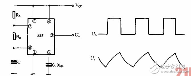
The 555 time base circuit can be used to form various types of self-excited multivibrators. The basic circuit is shown in Figure a. When the circuit is just turned on, since C is too late to charge, the 2 pin of the 555 circuit is at zero level, causing its output 3 pin to be high. When the power supply is charged to Cc to Vcc through RA and RB, the output terminal 3 is changed from the high circuit to the low level, and the capacitor C is discharged through the RB and the discharge switch of the internal circuit. When discharging to Vc ≤ Vcc, the output is converted from a low level to a high level. At this point, the capacitor is recharged, and this process can be repeated to form a self-oscillation. Figure (b) shows the waveform of the voltage at the output and capacitor C.
Incremental encoders provide speed, direction and relative position feedback by generating a stream of binary pulses proportional to the rotation of a motor or driven shaft. Lander offers both optical and magnetic incremental encoders in 4 mounting options: shafted with coupling, hollow-shaft, hub-shaft or bearingless. Single channel incremental encoders can measure speed which dual channel or quadrature encoders (AB) can interpret direction based on the phase relationship between the 2 channels. Indexed quadrature encoders (ABZ) are also available for homing location are startup.
Incremental Encoder,6Mm Solid Shaft Encoder,Hollow Rotary Encoder,Elevator Door Encoder
Jilin Lander Intelligent Technology Co., Ltd , https://www.jllandertech.com