![<?echo $_SERVER['SERVER_NAME'];?>](/template/twentyseventeen/skin/images/header.jpg)
Some MCUs (such as the 8098) have special reset instructions. Although some enhanced MCS-51 system MCUs do not have reset instructions, but the on-chip WATCHDOG circuit is integrated, anti-interference is not a problem. Since the popular MCS-51 series single-chip microcomputers (such as the 8031 ​​and 8032) have no reset instructions and do not have hardware WATCHDOS, if there is no external hardware WATCHDOG circuit, software anti-jamming technology must be used. Commonly used software anti-jamming technologies are: software traps, instruction redundancy, software WATCHDOG, etc. Their role is to detect when the system is disturbed, and then use the software method to reset the system. The so-called software reset is to use a series of instructions to imitate the reset operation, which is the unique software reset technology of the MCS-51 series microcontrollers.
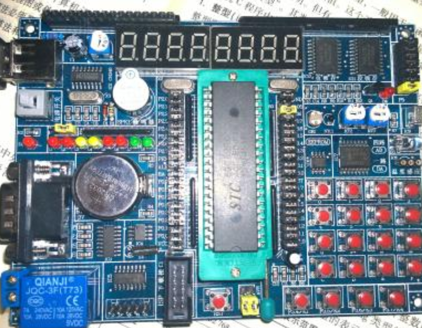
A simple experiment is now used to illustrate the experimental circuit as shown in the figure. The light-emitting diode LED0 connected to the emulation socket P1.0 is used to indicate the working status of the main program and is connected to P1. The light-emitting diode LED1 is used to indicate the operation of the low-level interrupt subroutine and is connected to the light-emitting diode LED2 of P1. To indicate the working status of the advanced interrupt subroutine, followed by P3. The 2-port button is used to set up the interference flag. After the program detects the interference flag, it deliberately enters into an infinite loop or falls into a trap to imitate the disturbed situation, thus verifying various The actual effect of the reset method. The inspection initialization procedure is as follows:
ORG 0000H
STAT: LJMP MAIN ; reset entry address
LJMP PX0 ; Button interrupt vector (low-level interrupt)
ORG 000BH
LJMP PT0 ;t0 interrupt vector (low-level interrupt)
ORG 001BH
LJMP PT1 ; T1 interrupt vector (advanced interrupt)
ORG 0030H
MAIN:
CLR EA
MOV SP, #7
MOV P1, #0FFH
MOV P3, #0FFH
MOV TMOD, #11H
CLR 00H; Interference Flag Initialization
SETB ET0
SETB ET1
SETB EX0
SETB PT1
SETB TR0
SETB TR1
SETB EA
LOOP: CPL P1.0; main program LED flashes
MOV R6, #80H
MOV R7, #0
TT1:
DJNZ R7, TT1
DJNZ R6, TT1
SJMP LOOP
PX0:
SETB 00H ; Set up interference flags to simulate interference
PT0: CPL P1.1; Low Interruption Program LED LED1 Flashing
RETI
PT1: CPL P1.2; Advanced Interrupt Program LED2 Flashing
RETI
END
The experimental steps are as follows:
1. Start the execution according to the above procedure. The three LEDs should be flashing (otherwise the fault should be eliminated first), indicating that the main program and each interrupt subroutine are normal. Because the analog interference flag is not detected, it is not affected by the button.
2. The main program is modified as follows. After the button is pressed, the main program is dropped into an infinite loop.
LOOP: CPL P1.0
MOV R6, #80H
MOV R7, #0H
TT1: DJNZ R7,TT1
DJNZ R6, TT1
JNB 00H, LOOP ; No interference?
STOP: LJMP STOP ; fall into an infinite loop.
At this time, you can see that the main program stops working (LED0 stops blinking), and the two interrupt subroutines continue to run (LED1 and LED2 continue to flash).
3. The timer T1 is constructed as software WATCHDOG and the 30H unit is used as software WATCHDOG counter. The main program adds a command to reset the software WATCHDOG.
LOOP: CPL P1.0
MOV 30H,#0 ; Reset Software WATCHDOG Counter
LOOP: CPL P1.0
MOV R6, #80H
MOV R7, #0H
TT1: DJNZ R7,TT1
DJNZ R6, TT1
JNB 00H, LOOP ; No interference?
STOP: LJMP STOP ; fall into an infinite loop.
The T1 interrupt subroutine is modified as follows:
PT1: CPL P1.2; Advanced Interrupt Program LED Blinking
INC 30H
MOV A, 30H
ADD A, #0FDH
JC ERR; reached 3 times no?
RETI
ERR: LJMP STAT; Software WATCHDOG Action
When the button is pressed, the program runs normally (three LEDs flash). After the button is pressed, the main program can quickly resume work, but the two interrupt subroutines are blocked and no longer work. The process is as follows: After the main program detects interference, it enters an infinite loop and cannot perform the operation of resetting the 30H unit. The T1 interrupt causes the 30H to increase continuously. When the count reaches 3, the software WATCHDOG performs an action and executes an LJMP instruction to execute the program from the beginning. The interference flag is cleared during the MAIN process (indicating that interference has passed), allowing the main program to quickly resume operation. It stands to reason that the MAIN process also resets each interrupt and opens them. Why can't the interrupt resume working? This is because the reset operation of the interrupt activation flag is forgotten because it does not have a clear bit address to program, and a direct return to the 0000H address does not complete a true reset. Software reset is the work that must be done after using the software trap and software WATCHDOG. At this time, the program error may be interrupted. In the subroutine, the interrupt activation flag is set and it will stop the peer interrupt response. Since software WATCHDOG is an advanced interrupt, it will block all interrupt responses. From this we can see that the importance of clearing the interrupt activation flag has led many authors of the literature to fail to recognize this as a misunderstanding.
4. Of all the instructions, only the RETI instruction can clear the interrupt activation flag. The error handler ERR mainly completes this function, and other aftermath tasks are completed by the reset system. For this reason, we redesigned the T1 interrupt subroutine as follows:
PT1: CPL P1.2; Advanced Interrupt Program LED Blinking
INC 30H; Software WATCHDOG Counter Value Added
MOV A, 30H
ADD A, #0FD
JC ERR; reached 3 times no?
RETI
ERR: CLR EA ; Off Interrupt
CLR A; Ready to Reset Address (0000H)
PUSH ACC
PUSH ACC
RETI ; Clear interrupt activation flag and reset
This program closes the interrupt first, so that the subsequent processing can proceed smoothly, and then replaces the LJMP instruction with the RETI instruction, thereby clearing both the interrupt activation flag and the task of turning to 0000H. After such a change, the program is run again, and the result is still not ideal: After the button is pressed, sometimes only the main program and advanced interrupt subroutine can quickly return to normal, and the low-level interrupt may still be closed. If the interference is transferred to the low-level interrupt as follows, the low-level interrupt must be closed after the button is pressed:
LOOP: CPL P1.0
MOV R6, #80H
MOV R7, #0H
TT1: DJNZ R7,TT1
DJNZ R6, TT1
SJMP LOOP
PT0: CPL P1.1
JB 00H,STOP
RETI
STOP: LJMP STOP ; fall into an infinite loop.
After careful analysis, it may be concluded that when the software WATCHDOG is nested in the low-level interrupt, only the advanced interrupt activation flag is cleared after the reset, and the low-level interrupt flag is still set, so that the low-level interrupt is always closed.
5. The modification error processing is as follows:
ERR: CLR EA; correct software reset entry
MOV 66H, #0AAH ; Rebuild power-on flag
MOV 67H, #55H
MOV DPTR, #ERR1 ; Prepare first return address
PUSH DPL
PUSH DPH
RETI ; Clear Advanced Interrupt Activation Flag
ERR1: CLR A
PUSH ACC
PUSH ACC
RETI ; clear low-level interrupt activation flag
At this time, RETI must be performed twice to reach 0000H to ensure that all interrupt activation flags are cleared and the same effect as hardware reset is achieved. Similarly, software traps must also have the following three instructions
NOP
NOP
LJMP STAT
Change to:
NOP
NOP
LJMP ERR
To achieve the goal.
When the main program is interfered with by the software trap, the interrupt flag is not set. In the execution of ERR, the RETI instruction is equivalent to the RET instruction, which can also achieve the purpose of software reset. Interested readers can replace software traps with infinite loops, replacing LJMP ERR with LJMP STAT and LJMP ERR1, respectively, and then setting the interference detection to low-level interrupts and main programs. The experimental results will inevitably prove that only LJMP ERR can guarantee absolutely. Realize the software reset, make the system get rid of the same interference and return to normal. During the software reset of the MCS-51 microcontroller, the interrupt return instruction RETI must be executed twice in succession.
Structure of Black Self-closing Split Sleeving
PET Wrap provides the same flexibility and abrasion resistance as the PET Expandable Braided Sleeving but with the added feature of a hook and loop closure running the length of the material.
This allows you to work on segments of the cabling, rather than having to remove the entire covering and re-run all of its contents.
Application of self closing sleeve
Self Closing Braided Wrap is widely used for management of A/V cableand power cord in home theater,computer ,TV support and so on.
Its ideal for application in wire harness, automatic equipment, railways, general manufacturing industry where wires and tubes need a tough and durable protection.
Usage is for the protection of wire and Tightening up, for computer power cord, audio-video, automotive, aviation , wire and cable industries.
Split Braided Sleeving,Cable Split Sleeving ,Split Wire Sleeve,Cable Sleeve Split Sleeving
Shenzhen Huiyunhai Tech.Co.,Ltd , https://www.hyhbraidedsleeve.com