When using a digital potentiometer to process an AC signal, the following factors need to be considered: First, the AC signal must be biased to the DC power supply voltage range; secondly, each level of the digital potentiometer usually only provides an equivalent resistance increase. End-to-end resistance can vary greatly between different devices. For example, some types of digital potentiometers can vary by ± 30%. (For more information, please refer to Application Note 161: Using a DS1802 Push-Button Digital PotenTIometer to Create an Audio Preamp with Attenuator and Application Note 1828: Audio Gain using Digital PotenTIometers for more informaTIon.)

For Larger Image
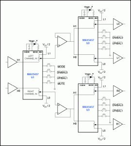
Figure 1. Using three MAX5456 / MAX5457 IC volume adjustment, equalization circuit
With the additional MAX5456 / MAX5467, volume control in a multi-speaker configuration can be achieved. The trigger / MODE input switches the working mode of the MAX5457 between volume control and equalization control. You can use the LED output to indicate two different modes. In the application circuit of Figure 1, U1 is used to control the balance and volume of the stereo input signal, and provides left and right channel output for the volume attenuator composed of U2 and U3. In the volume control mode, use the / DN \ / / BAL0 \ or / UP \ / / BAL1 \ keys of U1 to change the volume of the main controller. If you need to adjust the balance, trigger the / MODE \ pin to switch U1 to the balance mode and adjust it by / DN \ / / BAL0 \ or / UP \ / / BAL1 \.
U2 and U3 constitute the volume attenuation control of the left and right channels respectively. To adjust the balance of U2, the left channel signal from U1 is adjusted at L0 and L1; similarly, to adjust the balance of U3, the right channel signal from U1 is adjusted at R0 and R1. Refer to the MAX5456 / MAX5457 data sheet for volume and balance adjustment. Generally, U2 and U3 are not used to adjust the volume, but sometimes it can also be used to compensate for the mismatch of audio channels.
The pre-operational amplifier of U1 in the application circuit is used to linearly amplify or provide a high-impedance input for a stereo audio signal source to drive the MAX5456 / MAX5457. The minimum terminal resistance of the MAX5456 / MAX5457 IC is 7kΩ, and the equivalent impedance of the U1 left and right channel input terminals is 7kΩ (worst case), or 10kΩ (nominal value). The two amplifiers at the output of U1 act as buffers to limit the deterioration of the THD specification by the load. The four amplifiers at the output of U2 and U3 can reduce the potentiometer current and amplify the output signal to drive the speaker.
disease virus Antibody Test Kit /Antibody Test kit coronavirus
New Coronavirus antibody detection: assist clinical diagnosis, as a supplement indicators for nucleic acid detection
Test samples: serum, plasma, venous whole blood
Sample capacity: 10uL
Intended usage:
This kit is used for qualitative detection of New Coronavirus(2019-ncov) antibodies in human serum, plasma and venous whole blood samples in vitro.
It is only used as a supplementary test indicator for suspected cases with negative detection of New Coronavirus nucleic acid or used in conjunction with nucleic acid detection in the diagnosis of suspected cases. Restricted to medical institutions.
Antibody Test
Antibody Test Kit,Hiv Antibody Test Kit,Antibody Rapid Test Kit,Disease Antibody Test Kit
Guangzhou HangDeng Tech Co. Ltd , https://www.hangdengtech.com
![<?echo $_SERVER['SERVER_NAME'];?>](/template/twentyseventeen/skin/images/header.jpg)