![<?echo $_SERVER['SERVER_NAME'];?>](/template/twentyseventeen/skin/images/header.jpg)
Introduction The MAXQ1850 from Maxim Integrated Products is a high-performance, secure, small package, 32-bit RISC microcontroller designed for e-commerce, banking, and data security applications. The microcontroller executes 16-bit instructions and has a 32-bit data channel. The MAXQ1850 executes and completes most of the instructions in one clock cycle and is a very high-performance RISC machine. MAXQ1850 also has many important security features, including: Password accelerator supporting DES, 3DES, AES, SHA-1, SHA-224, SHA-256, RSA, DSA, and ECDSA True hardware random number generator 8KB low-leakage battery backup Electric NVSRAM 4 self-destructive input anti-tamper detection, can quickly erase the key / data. Environmental sensors capable of detecting over-range conditions (eg, temperature, voltage) The MAXQ1850 evaluation kit is an ideal platform for prototype development of safety applications. The kit provides an RS-232 serial port, two smart card slots (one full size, one SIM card), a USB connector, an LCD screen, a 16-key keyboard, and a prototype area.
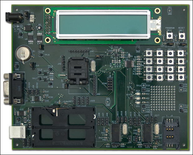
Setting up the MAXQ1850 evaluation kit The MAXQ1850 evaluation kit circuit board is shown in Figure 1. The hardware listed below is included in the evaluation kit to implement this application note: MAXQ1850 Evaluation Kit Circuit Board JTAG Circuit Board JTAG Cable (Connect MAXQ1850 Evaluation Kit Circuit Board and JTAG Circuit Board) 9-pin Serial Cable Power Supply 5V, ± 5%, 300mA, center positive)
Detailed circuit diagram (PDF, 776KB)
Figure 1. The MAXQ1850 evaluation board
Both the MAXQ1850 evaluation circuit board and the JTAG circuit board have many jumpers that need to be configured. If you need detailed information about jumpers and their functions, please refer to their respective data sheets. For this application note, please configure the jumpers as follows: On the MAXQ1850 evaluation kit circuit board, short-circuit the following jumpers: JU3 (near the Program switch); JU4 (near the Reset switch); JU30 (near the lower left of the processor) ; JU104 (near the lower left of the LCD module). Connect jumper JU5 (near the battery) and JU20 (near the power input) to pin 1 (square pad on the PCB) and pin 2. Connect pins 2 and 3 of jumper JU21 (near the upper right of the processor). All other jumpers should be opened. On the JTAG circuit board, short-circuit JH3. This provides 5V power from the JTAG board to the evaluation kit board. For this configuration, jumpers JH1 and JH2 are "don't care". Connect the JTAG cable between the JTAG circuit board and the MAXQ1850 kit circuit board. On the JTAG circuit board, the red bar on the cable should be connected to the side of the connector labeled Pin 1 and Pin 2. On the MAXQ1850 evaluation kit circuit board, the red bar on the cable should be connected to the side of the connector marked with pins 1 and 2 (pin 1 can be identified by the square pad on the back of the PCB).
Note that in the old MAXQ1850 evaluation board design, the MAXQ1850 microcontroller may have used a slot. If this is the case, insert the MAXQ1850 into the slot with its lead-free indicator "+" facing the point marked on a corner (lower right) in the slot.
Connect a 9-pin serial cable between your PC and the JTAG board (do not connect it to the MAXQ1850 kit board). Finally, connect the 5V power supply to the power connector (J2) of the JTAG circuit board. It also provides power to the evaluation kit circuit board.
Designed with the CrossWorks compiler: When WalkLED started using the MAXQ1850 evaluation kit, we developed a simple application that caused the three LEDs on the circuit board to blink. The LED flashes in a fixed, repeating sequence, and it looks like it is "walking" on the circuit board. Therefore, the project was named WalkLED. The code for this program is listed in Appendix A. The codes are very short, and you can even enter them manually in a relatively short time. You can also obtain the source code files from the CD of the evaluation kit or download them from the Maxim website.
The toolkit we used was CrossStudio provided by Rowley Associates. At the time of writing this document, the toolkit is CrossWorks for MAXQ30, version 2.0.0.2008063000.2293. This is the version used to generate screenshots in this document. To determine whether it is the latest version, please visit the Rowley & Associates website, or send an email to var name = "micro.support @"; var domain = "maxim-ic.com"; document.write ("" + name + domain + ""); micro. (English only).
When creating a new solution, click File
 New New Project. In the New Project pop-up box, fill in the Name and LocaTIon boxes at the bottom, select the Executable class from the Project Templates window, and the AC executable file (Figure 2). We will call the project WalkLED_demo and put it in the directory C: \ work \ maxq \ MAXQ1850 \ WalkLED_demo.
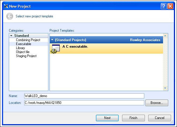
Figure 2. New project
Click Next to continue and you will see the Project ProperTIes pop-up box (Figure 3). The Target processor may be MAXQ1103. Double-click the processor serial number and select the MAXQ1850 processor. All other parts of this page and subsequent pages are selected by default, so after selecting MAXQ1850, click Finish to build the project. If necessary, you can click Next to select other engineering options.
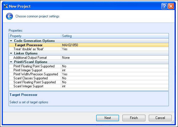
Figure 3. Select the MAXQ1850 processor
When creating a project, a new project will appear in the Project Explorer window (Figure 4), usually located in the upper right of the application window. Open it and you will see two folders, Source Files and System Files. Open Source Files and you will see main.c, which is the source code of your application. Double-click it to open it.
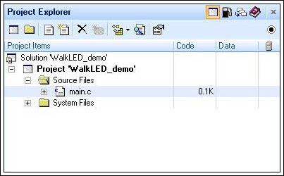
Figure 4. Project Explorer window
Now, enter the application code in Appendix A, or cut and paste the code into the main.c file from the source mentioned above, replacing all current content.
As the application executes, you will see LEDs DS1, DS2, and DS3 (located on the left side of the kit board prototype area) blinking in sequence. Before an application can run, it must first be "built". Choose Build
Build WalkLED_demo, or press F7. If everything is built correctly, you will see the message "Build complete" in the Output window with a check mark next to it (Figure 5). If there are errors, please make sure that the code you entered is correct. 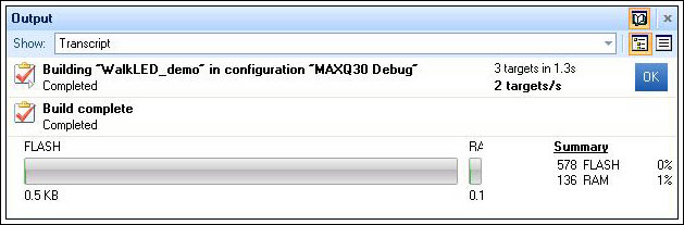
Figure 5. Output after project construction
You can now run the application. For this, click Debug
Build and Debug, the program will start and continue to run. Click the Pause button (Break ExecuTIon, as shown above and to the left of the code window), the program pauses at the current position, waiting for the user's next action. If there are no Build and Debug options, find the "targets" window; click Maxim Serial JTAG Adapter; then, click the Connect button (upper left corner of the window). In this way, the toolkit and evaluation kit are connected through the JTAG circuit board to enable the debugging function. After the toolkit debugging function is enabled, click the Step Over button to start the debugging process, as shown in Figure 6. 
Figure 6. Step Over button
Press the Step Over button. After the program starts, CrossStudio downloads the application to the MAXQ1850 through the JTAG circuit, and the Output window displays a status message. The application starts to run, and then stops on the first line of code (yellow arrow is displayed in the blank space on the left). When running the application from this point, select Debug
Go (or click the Play button). Now, make sure that the LEDs on the MAXQ1850 circuit board are blinking. You may want to be able to modify the application to some extent; flash the LEDs in the reverse order, or change the lighting time to flash faster or slower. Debugging applications with CrossStudio Now, let's understand the debugging capabilities of the MAXQ1850 and CrossStudio tools. The MAXQ1850 has a built-in JTAG engine that supports debugging on the actual chip, thereby eliminating the need for expensive emulators or emulators that can go wrong. Note that the MAXQ1850 also provides a safety lock mechanism to prevent JTAG from working when the component is locked. In this way, when the MAXQ1850 device is used in sensitive applications, it ensures that the JTAG debug engine does not pose a security threat.
Consider the WalkLED_demo application. As an experiment, in the main.c function, the delay count of the Delay function is changed from 200000 to 2000.
for (i = 0; i <2000; i ++); Now, select Build
Build and Debug, build and run the application. The toolkit will rebuild the project, load the new program, and start running. Note that the LED is always on, not blinking. Select the Pause button (or select Debug
Break), the program is suspended at the current line of code, and a yellow arrow appears in the blank area on the left. Since the program spends most of its time in the "for" loop of the Delay function, the code is likely to stop here (see Figure 7). 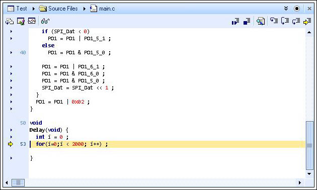
Figure 7. In the Delay function, the code stops running
Observe the Locals window on the right (if you cannot see this window, click Debug
Debug Windows Locals). This window will display the current value of the "i" variable. Now, press the Step Over button. Let the program run for one second, then, press the Pause button again. You should see the "i" value increase. To exit the function, you should keep pressing the Step Over button until the end of the loop, but this will waste a long time. As long as you press the Step Out button (to the right of the Step Into button, as shown in Figure 6), the program continues to execute until you exit the Delay function and return to its calling function main.c.
By setting breakpoints, similar results can be obtained. In the function main.c, when setting a breakpoint on any line calling the Delay function, click the small triangle to the left of the line of code. It will turn into a red circle (Figure 8). Now, run the application again (Debug
Go, or Play button). The application will run to this point and then pause. 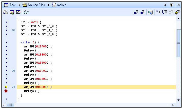
Figure 8. Add breakpoint
Now, let's understand more debugging functions. Press the Step Over button several times. Each press, the C source code executes a line. You will see that the LED blinks every time a line of code that controls the LED is executed. When paused on the Delay () line, press the Step Into button (Figure 9). This will enter the function and pause at the first line of the function. As demonstrated previously, you can exit the Delay () function by pressing the Step Out button.

Figure 9. Step Into button
At runtime, you can also change variables (and registers). Click GO, then click Pause, the program should stop again in the middle of the Delay () function. Note the "i" value. Now, set "i" to 1998 (click the value displayed by "i" and enter 1998 after highlighting). Click the Step Into button. Since the final value of "i" is reached, you will see the end of the loop.
And other debugging features that interest you: Debug
Disassembly will display both the C code and the generated assembly code. In this way, the user can enter the assembly code instead of the C code, and the C code is displayed at the same time when it is executed. Debug Debug Windows Call Stack will display the function called when the application reaches the current position. If execution is suspended in the Delay () function, its display is shown in Figure 10. Use Debug Stop to stop debugging and observe the Targets window on the right. Make sure that Maxim Serial JTAG Adapter ProperTIes is displayed in bold, and observe the information at the bottom of the Properties Window. If Maxim Serial JTAG Adapter Properties is not displayed, select it from the drop-down menu. You will see a list of attributes and their settings, as shown in Figure 11. Use the scroll bar to see all the information. An attribute under the Connection heading is Port Name. If you use a serial port instead of the default COM1, you can change this option here. 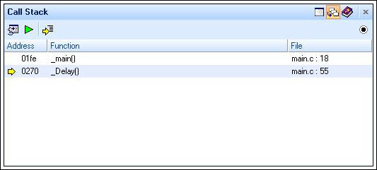
Figure 10. Call stack while running in Delay () function
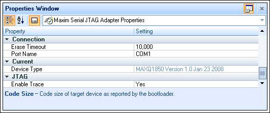
Figure 11. Properties window
More information Software libraries and reference designs are currently being developed by Maxim engineers. If you need the latest information about libraries and tools, or have other questions about this application note, please contact var name = "microcontroller.support @"; var domain = "maxim-ic.com"; document.write ("" + name + domain + ""); microcontroller. (English only).
Appendix A. WalkLED_main.c source code #include
SPI is a trademark of Motorola, Inc.
Babbitt Wire is with tin as the base, the product is added with certain amount of antimony, copper
or other improved elements.
Sn Sb7Cu3 Babbit metal is suitable for metal spraying on the end face of metalized ï¬lm capacitor. With strong adhesive force, good weldability and low loss angle, it is an ideal metal spraying material for laminated capacitor.
Other trade marks are suitable to use CMT, TIG and MIG technology to manufacture sliding bearing bush material layer. It is of high bonding strength with substrate, with material utilization rate of 70~80%. It has small amount of ingredient segregation without any loose or slag inclusion. The internal control standard of the alloy composition is prevailing over GB/T8740-2013. Babbi1 metal added with improved elements can substantially enhance the service life.
Snsbcu Babbitt Wire,Overlaying Materials,Thermal Spray Babbitt Wire,Babbitt Wire
Shaoxing Tianlong Tin Materials Co.,Ltd. , https://www.tianlongspray.com