![<?echo $_SERVER['SERVER_NAME'];?>](/template/twentyseventeen/skin/images/header.jpg)
Hybrid and electric drive systems used in cars, trucks and motorcycles have created new and previously unknown challenges in the transportation industry. The original 12V voltage network is now complemented by a 400V or higher battery and power system, which sets new requirements for automotive OEM and system module suppliers. Isolation requirements are proposed for all functions in hybrid/electric vehicles such as high voltage batteries, DC/DC converters, inverters for driving motors, and on-board charger modules connected to the 230V/380V grid.
This article refers to the address: http://
Automotive and transportation applications have different requirements for isolation than industrial applications. Solid and reliable is of course necessary, and magnetic "noise" must also have strong resistance. The high power level in the car (such as a 100 kW motor operating at 400 V, meaning 250 A operating current) will generate a strong magnetic field in the car that must be properly handled. The parts used must be long enough to meet the life expectancy requirements of the vehicle; for example, must meet the decades of use requirements for large-scale transportation applications. Products for the automotive environment will drive the quality of automotive applications (Q1) and operate over the -40 to +125 °C operating temperature range.
At the same time, cost pressures in these areas will drive higher system integration requirements, so single-chip products with isolation, such as CAN transceivers, ADCs or gate drivers, offer advantages.
Different digital isolation techniques
In principle, there are four different methods of digital isolation: optical, inductive, capacitive and RF. The first three methods are described below.
Optical isolation technology uses a transparent insulating isolation layer for optical transmission to achieve optical isolation. By driving LEDs (light-emitting diodes), digital signals are converted from electricity to light. The optical signal is then transmitted through the isolation layer, and the optical signal is converted back to the electrical signal by an optical detection component (photodiode, phototransistor).
The main advantage of optical isolation is that light is immune to electric or magnetic fields and has the potential to deliver static signals. At the flipside of the isolation layer, the operating frequency (transmission speed) of the optical isolator is limited by the relatively slow nature of the LED. For hybrid/electric vehicle applications, the limited lifetime of optical isolation is a major drawback. Over time, the efficiency of the LED will decrease, requiring a larger signal drive current (usually starting at 10 mA), so this optical isolation will not function as time goes by.
Inductive isolation uses a change in the magnetic field between the two coils to enable communication across the isolation barrier. One advantage of the inductive isolation method is the difference between common mode and differential transmission, which means that it has good noise immunity. The disadvantage of this approach is that it can be due to distortion of the magnetic field, which is common for motor control environments in hybrid/electric vehicle applications.
Capacitive isolation utilizes the electric field variation across the isolation barrier. The benefits of capacitive isolation are greater immunity to magnetic fields and longer system life. Capacitive isolation is similar to the transmission speed of the inductive isolation method.
However, the disadvantage of capacitive isolation is that there is no differential signal (ie, the signal and noise share the same channel). In addition, as with the inductive isolation method, they cannot directly transmit static signals (which must be encoded with the frequency signal first).
Isolation product
An example of a capacitive isolation method is the ISOxxxx series from Texas Instruments. Figure 2 is a simplified architecture diagram of the ISO72xx system. The ISOxxxx component integrates two bare crystals placed on separate leadframes, as well as transmit and receive chips, in a single package. The two bare crystals are connected by only one bonding wire. The actual isolation function implemented on the receiver is based on silicon dioxide (SiO2, glass) with copper and doped silicon as the substrate electrode capacitor (Figure 3). The use of SiO2 offers the advantages of high reliability and long life.
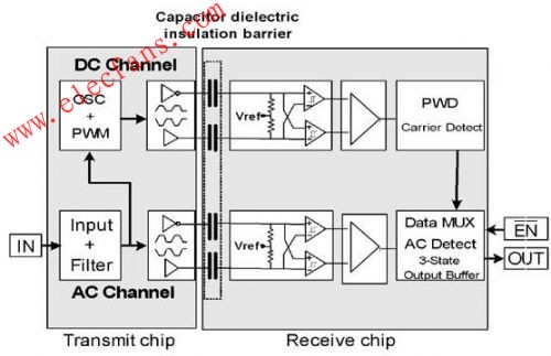
Figure: TI's ISO 72xx series architecture diagram.

Figure: TI's ISO72xx series of dies, with the silicon dioxide isolation on the receiver chip on the right.
Both channels allow both DC and AC communication, and it also has a fail-safe feature.
The basic AC channel uses the input signal and, after filtering, transmits the signal through a differential pair consisting of isolated capacitors. Then, the input of the Schmitt trigger on the receiving chip is detected, and finally the received signal is output through the output buffer. It achieves very high speed transmission, slight pulse width distortion and short transmission delay, but does not transmit DC signals.
A DC channel can be used to transmit a DC (or very low speed) signal through an isolation barrier. The on-chip oscillator encodes the signal as a PWM signal, which is transmitted across the isolation barrier by a differential signal similar to the AC channel. At the receiving chip end, the signal is decoded and sent to the output buffer.
However, the DC channel is also used for fault prevention. For example, if the power supply voltage at the transmitter is not high enough, the oscillator will stop working, which means that the receiver will not detect the data signal, which will give a fault indication and output a high level. In normal operation (ie, there is sufficient data transmission density), the output multiplexer will ignore the DC channel; but when the AC channel has no data transmission for about 4 us, the DC channel will get priority. Once the AC signal has a transition, the multiplexer will immediately switch back to that channel.
A variety of isolation components are available to meet different configurations (single to four). They are capable of providing 560V continuous insulation (4kV peak transient) at data rates up to 150Mbps. In addition, these components meet automotive-grade application requirements.
Reliability considerations and external electromagnetic field immunity
The harsh automotive and transportation environment, combined with the long service life of the vehicle, requires components with special characteristics. Mean Time Between Failure (MTTF) is a standard method for determining the reliability of semiconductor circuits. For the isolation component, it applies to both the integrated circuit and the isolation principle. It should be evaluated with a 90% confidence level and an ambient temperature of 125 °C. The average fault-free time for typical capacitor and inductor components is over 2,000 years, while the FIT (number of failures in 109 hours) is within 60. The average time between failures of typical optical components is only 30 years, and the FIT is nearly 4,000.
In terms of immunity to magnetic fields, Figure 4 compares the inductive and capacitive components. Both inductive and capacitive components (ISO721) have high magnetic field immunity far beyond the IEC61000 standard. However, the capacitive component ISO721 is superior, which is especially important for harsh automotive environments.
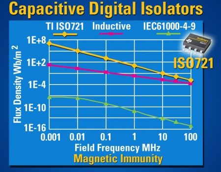
Figure: Immunity to an external magnetic field.
Lithium Battery,Lithium Batteries,Lithium Polymer Battery,Lithium Iron Phosphate Battery
Power X (Qingdao) Energy Technology Co., Ltd. , https://www.qdpowerxsolar.com