![<?echo $_SERVER['SERVER_NAME'];?>](/template/twentyseventeen/skin/images/header.jpg)
The inverter converts DC power (battery, battery) into alternating current (typically 220V, 50Hz sine wave). It consists of an inverter bridge, control logic and filter circuits.
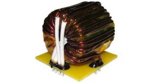
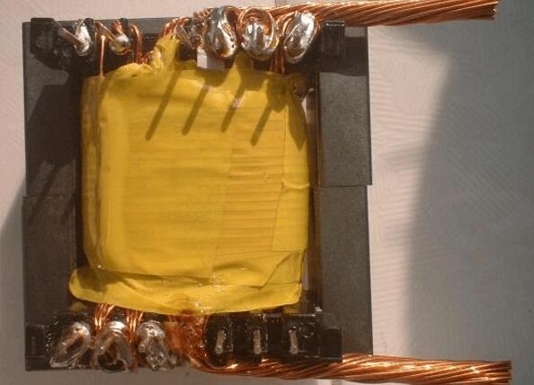
Inverter transformer structure characteristics1. The coil is made of F-grade or C-grade paint multi-cake type, which is arranged closely and evenly. The outer surface does not contain insulation layer, which has excellent aesthetics and good heat dissipation performance.
2. The core joint is welded by sub-arc welding. After the coil and the iron core are assembled into one body, the process of pre-baking → vacuum dipping → hot bake curing makes the coil and iron core of the transformer firmly combined, not only greatly reduced It reduces the noise during operation and has a very high heat resistance rating.
3. The exposed parts are treated with anti-corrosion treatment, and the terminals are connected by terminal blocks or copper-plated terminals.
Its working principle flow is that the control circuit controls the operation of the whole system. The inverter circuit completes the function of converting from DC to AC. The filter circuit is used to filter out unwanted signals. The working process of the inverter is like this. The operation of the inverter circuit can be further refined as follows: first, the oscillating circuit converts the direct current into alternating current; secondly, the coil boosts the irregular alternating current into a square wave alternating current; finally, the rectification causes the alternating current to become a sinusoidal alternating current via the square wave .
The inverter (see Figure 1) introduced here is mainly composed of a MOS field effect transistor and a common power transformer. Its output power depends on the power of the MOS FET and the power transformer, eliminating the cumbersome transformer winding, suitable for electronic enthusiasts in amateur production. The working principle of the inverter is described below.
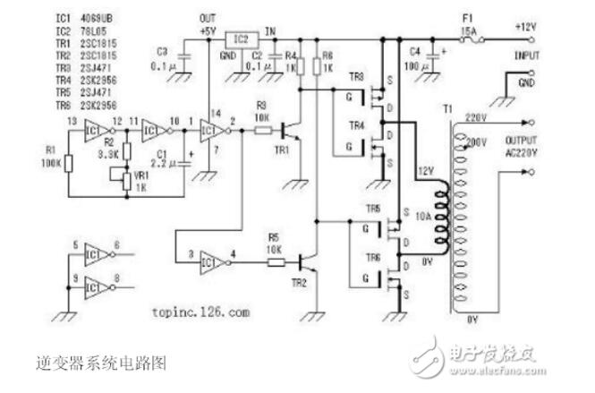
Here we will detail how this inverter works.
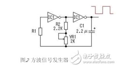
Here, a six-inverter CD4069 is used to form a square wave signal generator. In the circuit, R1 is a compensation resistor for improving the oscillation frequency instability caused by the change of the power supply voltage. The oscillation of the circuit is completed by charging and discharging the capacitor C1. The oscillation frequency is f=1/2.2RC. The maximum frequency of the circuit shown is: fmax=1/2.2&TImes;3.3&TImes;103&TImes;2.2&TImes;10-6=62.6Hz;minimum frequency fmin=1/2.2×4.3 ×103×2.2×10-6=48.0 Hz. Actual values ​​may vary slightly due to component errors. For other redundant inverters, the input is grounded to avoid affecting other circuits.
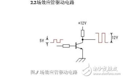
Since the maximum amplitude of the oscillating signal voltage output by the square wave signal generator is 0~5V, in order to fully drive the power switch circuit, the oscillating signal voltage is amplified to 0~12V by TR1 and TR2, as shown in Fig. 3.
One: Choose two strands of 0.72 enameled wire fixed at 6 feet (head of high voltage winding), wrap two layers of 35T, the other end should not be cut, wrap the insulation layer and start to round the primary.
Second: choose 6 strands of 0.72 line of neatly wrapped tape to be stuck between the 1, 2 feet of the skeleton, and also choose 6 strands of 0.72 line of neatly wrapped tape wrapped between the 3, 4 feet of the skeleton. So 12 strands are neatly arranged in a layer around 3T.
The 1 and 2 feet of the line are drawn between the 9, 10 feet and the appropriate length is cut. The same 3, 4 feet of the strand between the 12, 13 feet lead to leave the appropriate length cut.
In the same way, use the same method to spare (2,3)-(11,12), (4,5-13,14).
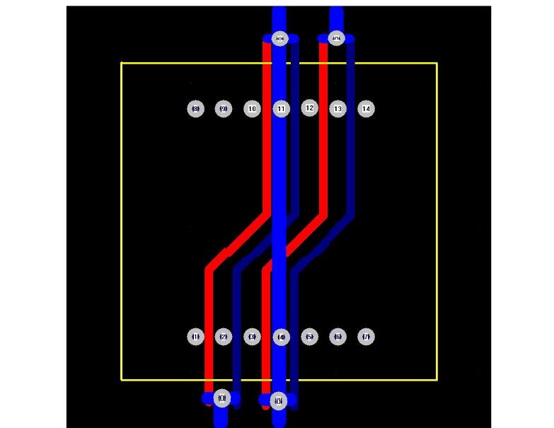
Three: Pack the insulation and connect the high voltage winding to continue to wrap the two layers of 35T high voltage winding. Do not cut off the end of the line.
Four: After wrapping the insulation, repeat the second step and repeat the winding side. The end of the thread is also in the same position.
Five: Pack the insulation and then connect the high-voltage winding to continue to connect the two layers of 35T high-voltage winding to complete the 7 feet.
This way the transformer is wound up. Look at the diagram and carefully analyze all the lines between the 1st, 2nd and 3rd feet and invite it to be a set of 3T heads, all the lines between the 12, 13 and 14 feet and please come another A set of 3T tails. The line between 3, 4, and 5 and the line between 10, 11, and 12 are the center taps of the two 3Ts.
After winding all the windings, the thickness of the whole line package is only 10 layers and the thickness of 0.72 is slightly larger than 7.2MM. The core skeleton of EE55 generally has about 9MM and is completely wound around this point.
Finally, all the thread ends are arranged on the tin. Consider the line between 3, 4, and 5 and the line between 10, 11, and 12 is inconvenient to connect at both ends, then the lead is left long when drawing the PCB. Reasonable wiring can be handled easily. In actual use, the line between 3, 4, and 5 and the line between 10, 11, and 12, leave a sufficient length to sleeve the sleeve and directly lead to the positive pole of the power supply.
Add one more point: When actually selecting the wire diameter, you can choose according to your existing enameled wire. But try to calculate how many strands are used in parallel, so that each layer is just full from the side of the skeleton to the other side. If you carefully use the window carefully, you can really achieve 800W.
Water-cooled Capacitor is supercapacitor is a capacitor with a capacity of thousands of farads.According to the principle of capacitor, capacitance depends on the distance between the electrode and electrode surface area, in order to get such a large capacitance, as far as possible to narrow the distance between the super capacitor electrode, electrode surface area increased, therefore, through the theory of electric double layer and porous activated carbon electrode.
Water-Cooled Capacitor,Water-Cooled Power Capacitor,Water-Cooled Electric Heat Capacitor,Water-Cooled Electric Heating Capacitor
YANGZHOU POSITIONING TECH CO., LTD. , https://www.cnchipmicro.com