![<?echo $_SERVER['SERVER_NAME'];?>](/template/twentyseventeen/skin/images/header.jpg)
1 Introduction
With the rapid development of MEMS technology, endoscopic technology has achieved significant research results, especially the human gastrointestinal tract wireless capsule endoscope is a major breakthrough in medical electronic endoscope systems. More and more research is being carried out around capsule endoscopes. However, wireless endoscopic capsules also have many problems. The 2004 European Technical Report pointed out that the realization of motion and posture control functions is the first problem to be solved, including motion control and positioning problems, and in order to ensure the diagnosis and treatment process. The effectiveness of motion and positioning problems is extremely important for real-time location detection of the spatial position of these miniature medical capsules in the body. In the aspect of the positioning technology of the micro-diagnostic device in the body, the traditional methods generally adopt the techniques of ultrasonic imaging, nuclear medicine imaging and fluorescence modeling positioning, but these positioning methods have high cost and complicated operation, which are easy to cause radiation and cannot meet the human body. The shortcomings of long-term dynamic positioning. Many scholars have carried out research on the device positioning system, and proposed a simplified model of magnetic positioning and corresponding dynamic tracking technology.
In order to better meet the requirements of permanent magnets for accurate positioning measurement of microcapsules in vivo, the author designed a three-axis magnetoresistive sensor module based on HMC1022 and HMC1021. After amplification by two-stage amplification circuit, the data acquisition device A positioning system for multi-point acquisition of capsule magnetic field strength. The system adopts a magnetoresistive sensor module with higher sensitivity than before, and the sensor module group is arranged reasonably, which has the advantages of higher detection sensitivity and large measurement range.
2. Capsule positioning detection principle
Magnetic induction positioning utilizes the Hall effect of a magnetoresistive sensor, that is, a magnetic field distribution of a specific law is formed in a spatial magnetic field according to a change in the direction and distance of a magnetic moment of a permanent magnet. Correspondingly, by detecting changes in specific magnetic field parameters, we are able to measure the change in the spatial position of the permanent magnet and determine its specific location in space.
In the human body, the capsule can be regarded as a rigid body. At the same time, cylindrical permanent magnets are placed inside the capsule for the purpose of positioning the magnetoresistive sensor module. As shown in Fig. 1, the positional posture of the capsule in space can be represented by the position of any point inside the inside and the two corners formed by the magnetic moment direction of the permanent magnet in the capsule and the cylindrical coordinate system, wherein the coordinates of the center point of the capsule are The angle between the direction of the magnetic moment of the capsule and the coordinate of the column, the coordinate system of the origin of the space.
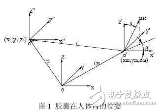
When the size of the cylindrical permanent magnet in the capsule is much smaller than the distance r from the magnetic sensor, the permanent magnet can be simplified into a magnetic dipole, and the magnetic induction of the capsule in the magnetoresistive sensor module can be directly written:
Where, the magnetic moment vector of the capsule is the vector position and coordinates of the capsule space, and is the position vector and coordinate of the magnetoresistive sensor module, which is the position vector of the magnetoresistive sensor module relative to the capsule. It is the size of the magnetic moment of the capsule, which is the coordinate of the three-axis magnetoresistive sensor module disposed in the space, and its coordinate axis coincides with the global coordinate system. From equation (1), the coordinates are known, and each magnetic field component is measured experimentally. At this time, if five unknowns are required to be solved, at least two three-axis magnetoresistive sensor modules are available.
3. System hardware design
The hardware of this system consists of four sets of three-axis magnetoresistive sensor module (built-in set/reset circuit), amplifier circuit and data acquisition card.
3.1 Magnetoresistive sensor module
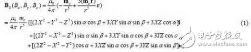
Figure 2 shows the designed three-axis magnetoresistive sensor module consisting of HMC1022 and HMC1021 installed perpendicularly to each other. The built-in set/reset circuit is used to measure the magnetic induction intensity of the strip magnet inside the space. HMC1022 The two directions (axis direction) (ie, in equation (3)) are measured, and the HMC 1021 measures the magnetic induction in one direction (axis direction) (ie, in equation (3)). The HMC1022 and HMC1021 are two-axis and single-axis magnetoresistive sensors, respectively, which have the same technical parameters except for measuring the number of axes of magnetic induction. The set/reset straps are integrated into the HMC1022 and HMC1021 to reduce temperature drift effects, nonlinear errors, and loss of output signals due to the presence of high magnetic fields.
3.2 Amplifying circuit
As the distance increases, the distribution of the magnetic field strength of the permanent magnet decays rapidly. In view of the above-mentioned variation of the magnetic field strength of the permanent magnet with distance, in the experiment, the typical amplifying device of AD620 is used to calculate the accuracy of the resolution of the data acquisition card, which is greater than the resolution accuracy of the output of the magnetoresistive sensor. A 1000x magnification was chosen in the experiment.
3.3 Data collection
The PCI-1716 data acquisition card is used to collect the output signal of the amplifying circuit into the computer for processing and analysis. The LABVIEW virtual instrument graphical software programming is used to realize the functions of collecting analog signals and A/D conversion.
4. Experimental steps
Figure 4 is a block diagram of the experimental steps.
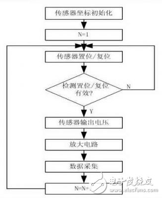
Figure 4 Experimental step flow chart
The experiment was carried out using the following procedure:
(1) When the sensor coordinate initialization experiment is performed, the spatial coordinates of the four sets of three-axis magnetoresistive sensor modules are fixed and recorded (ie, in equation (1)), and then brought into the formula (1) to solve the calculation after the acquisition is completed. .
(2) After each time the capsule moves and is fixed, the position distance between the capsule and each group of magnetoresistive sensor modules is recorded, and the sensitivity of the sensor is improved by the set/reset circuit integrated in the magnetoresistive sensor module.
(3) After the set/reset, the magnetoresistive sensor module outputs an effective magnetic field strength voltage, which is then amplified and collected by a voltage, sent to a computer for analysis and processing, calculated according to the above formula (1), and actually in step (1). Record the distance for comparative analysis.
5. Experiment and result analysis
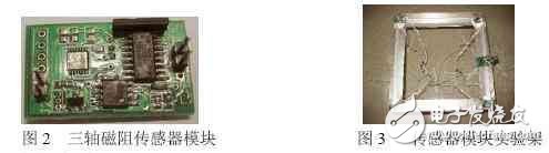
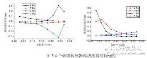
In the experiment, four magnetoresistive sensor modules were placed on the four apex angles of the cube-shaped experimental frame (0.3mx0.3mx0.2m), as shown in Figure 3, and their initial coordinates were sequentially fixed. During the acquisition process, the direction of the magnetic moment of the capsule is adjusted and the axis is positive. In the plane of the magnetoresistive sensor module, the capsule is positioned from the point along the straight line every 3 cm and gradually moved to the point. Four magnetoresistive sensor modules are in each After the secondary positioning, the data is collected sequentially. As shown in FIG. 5, the magnetic field strength measured by the magnetoresistive sensor module A is continuously decreased, and the magnetic field strength trends of the magnetoresistive sensor modules B and C are gradually approaching, and the magnetic field strength measured by the magnetoresistive sensor module D is slowly rising. Comparing the experimental data with the calculated data, it was found that the error between the two was within ±10%. The magnetoresistive sensor module set designed in this paper can accurately measure the magnetic induction intensity of the capsule during the movement.
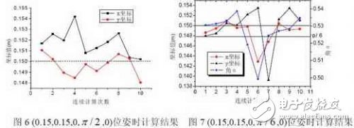
At the same time, for the three positions of the capsule, the result of the calculation for 10 consecutive times is performed. The selected pose points are (0.15, 0.15, 0, , 0) and (0.15, 0.15, 0, , 0). Figure 6 shows the results of the pose point (0.15, 0.15, 0, , 0). It can be seen from the figure that the calculated coordinate values ​​x and y fluctuate around 0.15 with an error of ±3%, while the axis coordinate value and two The calculation results of the angle values ​​are very ideal and are not marked. Figure 7 shows the results of the pose point (0.15, 0.15, 0, , 0), where the direction of the magnetic moment of the capsule and the axis angle are 30. From the fluctuation of the coordinate values ​​in the figure, the error is expanded to 7%, and the coordinate error with the axis is 5%. The calculation results of the other two parameters are ideal.
The above measurement experiments and calculation results show that the designed positioning detection system can accurately measure the magnetic induction intensity of the capsule during the movement, so as to accurately locate the spatial position and direction of the capsule. At the same time, it should be noted that when the capsule is in the middle of the measurement area of ​​the four magnetoresistive sensor modules, the accuracy of the calculation result is high.
6 Conclusion
In this paper, the author proposes a new experimental system to study the positioning technology, using high-sensitivity magnetoresistive sensor module to inductively collect the magnetic field strength of microcapsules. Both the principle and the experiment prove that the positioning of the micro endoscope capsule can be realized by detecting the spatial magnetic field distribution of the permanent magnet. The analysis of the experimental results proves that the positioning system has a high accuracy rate for the spatial position and orientation of the capsule during the movement, and can be effectively applied to the positioning of the micro endoscope capsule in the body, which significantly improves the clinical disease. The accuracy of the diagnosis.
The utility model provides a disposable electronic cigarette, comprising: a hollow shell, the bottom of the shell is provided with a lower cover; the shell contains an atomizer, and the outer side of the atomizer is sheathed with a disposable cigarette A bomb, a microphone cover is arranged under the atomizer, a microphone is covered under the microphone cover, a battery is arranged on one side of the atomizer, and an upper cover is arranged on the top of the casing; The atomizer includes an atomizing corThe utility model provides a disposable electronic cigarette, comprising: a hollow shell, the bottom of the shell is provided with a lower cover; the shell contains an atomizer, and the outer side of the atomizer is sheathed with a disposable cigarette A bomb, a microphone cover is arranged under the atomizer, a microphone is covered under the microphone cover, a battery is arranged on one side of the atomizer, and an upper cover is arranged on the top of the casing; The atomizer includes an atomizing core, an oil-absorbing cotton sleeved on the outside of the atomizing core, and an atomizer outer tube sleeved on the outside of the oil-absorbing cotton. The disposable electronic cigarette provided by the utility model absorbs the smoke oil on the surface through the absorbing cotton, and then atomizes the smoke through the atomizing core, which greatly reduces the risk of oil leakage, at the same time, reduces the burning of cotton and ensures the smoking taste.e, an oil-absorbing cotton sleeved on the outside of the atomizing core, and an atomizer outer tube sleeved on the outside of the oil-absorbing cotton. The disposable electronic cigarette provided by the utility model absorbs the smoke oil on the surface through the absorbing cotton, and then atomizes the smoke through the atomizing core, which greatly reduces the risk of oil leakage, at the same time, reduces the burning of cotton and ensures the smoking taste.
disposable vape,vape pen,vape accessories,vape store,vape battery,e-cigarettes,Disposable Pod
Suizhou simi intelligent technology development co., LTD , https://www.msmvape.com