![<?echo $_SERVER['SERVER_NAME'];?>](/template/twentyseventeen/skin/images/header.jpg)
The first professional oscilloscope I've used is an old one. It is an art to get a stable display on an old oscilloscope. Now I like all the triggering tools, even the most basic oscilloscope triggering tools.
The oscilloscope trigger system synchronizes the time base of the oscilloscope with the input signal, resulting in a stable display. In an analog oscilloscope, the trigger system starts the sweep generator so that the horizontal sweep synchronizes with the vertical signal. Digital Storage Oscilloscopes (DSOs) produce the same effect in different ways. In the DSO, digitizers work continuously, trigger events mark relevant data in the acquisition memory, lock the signal data for display, measurement, and further processing.
Today's DSOs include relatively simple edge triggers, complex "smart" triggers, and more sophisticated "enhanced" triggers. Let's take a look at these different trigger implementations.
Edge trigger
Edge triggering is the most commonly used trigger method. The principle of edge triggering is that the oscilloscope triggers when the trigger source trace exceeds the trigger threshold level at a user-specified slope (positive, negative, or any). Before the oscilloscope triggers, the signal is required to transition through the hysteresis interval, and the triggering hysteresis provides noise immunity. Most oscilloscopes use a hysteresis level of 0.3 to 0.5 vertical divisions.
Trigger sources include input channels, external trigger inputs, line power, and, in some cases, a built-in fast edge signal. The slope, polarity, and trigger threshold of each trigger source can be set independently of other trigger sources. Figure 1 shows the edge trigger setup for a typical mid-range oscilloscope.
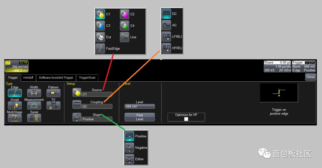
Figure 1: Elements of edge trigger settings include trigger source, level, slope, and coupling.
In addition to setting the trigger source, trigger level and slope, there are coupling options: AC or DC coupling and low or high frequency rejection. Frequency-selective coupling paths are used to attenuate irrelevant signals. Low-frequency suppression inserts a 50 kHz high-pass filter in the trigger signal path, and high-frequency suppression uses a 50 kHz low-pass filter. These frequency selective coupling modes are suitable for applications such as fault diagnosis of switching power supplies. High-frequency suppression makes it easier to trigger the mains-related signal, and low-frequency suppression simplifies the triggering of the switching regulator signal.
Some oscilloscopes have a "Find Level" button. Press this button and the oscilloscope will automatically find the trigger level of the current trigger source. Another convenience is the use of a trigger icon (right side of Figure 1) to summarize the trigger settings.
Trigger isolation
Trigger isolation is a trigger function used when each acquisition contains multiple trigger events. It lets the oscilloscope ignore additional trigger events and stabilize the display, just as if there was only one trigger event per acquisition. Trigger isolation can be based on time or trigger events. Figure 2 shows an example of time-based trigger isolation. The waveform being acquired is 8 bursts with a duration of 7 μs.
There are eight possible trigger events. A trigger event is a signal condition that normally causes the oscilloscope to trigger. You can think of trigger isolation as a command whose role is to ignore triggers that occur at the specified time or number of events.
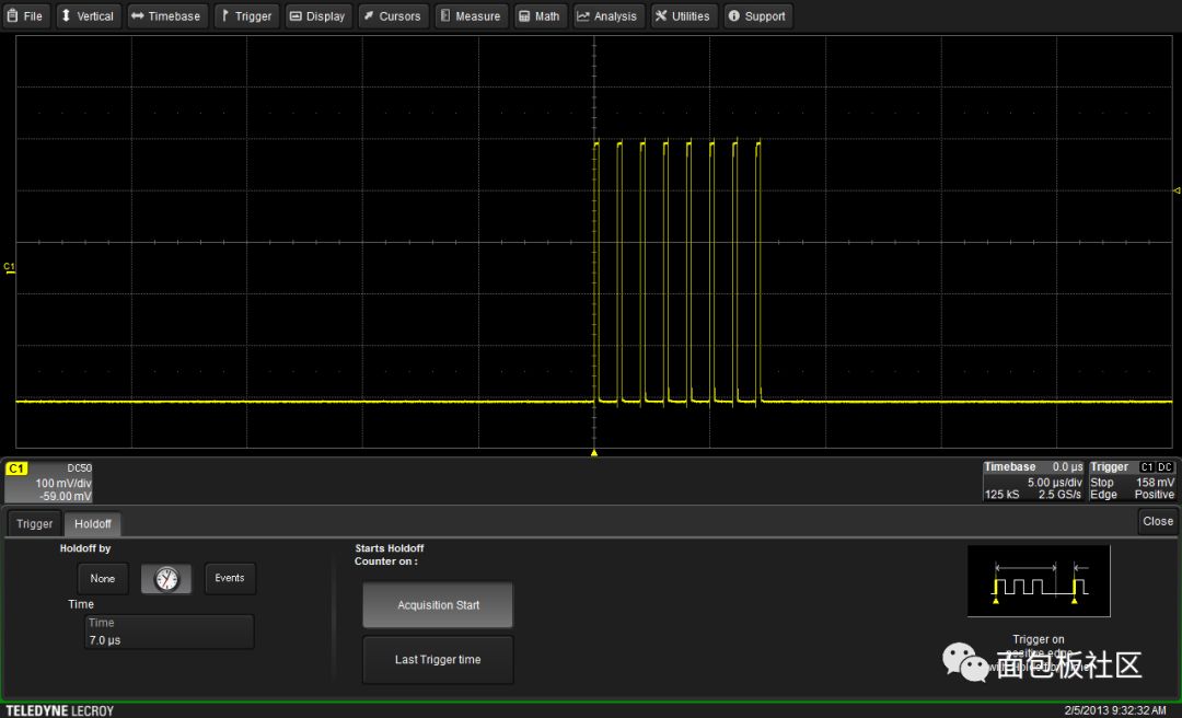
Figure 2: A time-based isolated trigger can achieve a stable trigger on a burst waveform (7μs duration from the first to the last positive edge).
In Figure 2, the isolation is set to ignore the trigger when the burst duration is 7 μs. When the oscilloscope trigger function is activated, there will be a 7μs interval after any trigger. Because the duration of the burst is 7μs, the next trigger will be at the beginning of the next burst.
Event-based isolation has the same effect. In this example, isolation is achieved by eight trigger events. This is the entire duration of the burst. Again, the acquisition will be synchronized with every burst. Please note that isolation does not guarantee that the trigger occurs at a particular point in the burst, but only in synchronization with the burst. Synchronization will be maintained until the signal is interrupted. When the connection is restored, it will be resynchronized, but it may be at a different point.
The "Start Isolation Counter" determines whether the isolation counter is cleared at the beginning of each acquisition (choose "Start of acquisition") or continue to accumulate ("Last triggered time" is selected). Remember that the trigger input is always active. If a trigger pulse arrives, counting may occur under isolated conditions even during the acquisition process, unless the isolation counter is restarted at the beginning of the acquisition. Similarly, if the process that is being synchronized with is continuous, you can choose to count all trigger events starting from the last trigger time.
Trigger isolation is a useful tool, but using it does require some experience. It may be helpful to review the oscilloscope manual and any application notes or tutorials provided by the manufacturer.
Smart trigger
Mid-range oscilloscopes often contain a powerful set of intelligent triggering systems that are based on the timing and magnitude parameters of the trigger signal. Smart triggers may include glitches, widths, windows, intervals (periods), missing codes, logic patterns, runts, TV, and slew rates.
Below we use width trigger as an example of smart trigger. Width triggers are sensitive to signal width and are typically applied to rectangular pulses. The provisions of trigger conditions such as "pulse wider than", "pulse narrower than", "in range", and "out of range" make it a powerful tool for triggering complex signals.
The waveform shown in Figure 3 is used to demonstrate how to use the width trigger feature. This is a pulse width modulated waveform with 8 different widths from 500ns to 4μs.
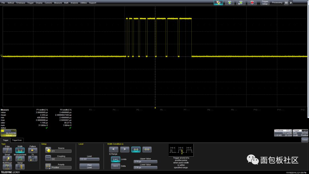
Figure 3: Using the width trigger function to trigger the oscilloscope at a pulse width of 2.5 μs.
As mentioned earlier, the trigger can be defined using four width conditions. Figure 3 shows the width-triggered pulse width between 2.3 μs and 2.7 μs. The width trigger dialog of Figure 3 shows the settings triggered under the "in-range" width condition. Pulses with a width of 2.5 μs are trigger events. Other smart triggers work similarly and can provide a variety of trigger events based on signal characteristics.
Exclude trigger
Exclude trigger is triggered when the waveform is abnormal, but avoid triggering in the case of "normal" waveform. It is based on smart triggers that use "out of range" triggering conditions. Exclusion triggers can be used to find waveform anomalies and glitches. The main advantage of using exclusion triggering is that no anomalies need to be known, because the triggering is based on the easily measured nominal waveform characteristics.
Figure 4 is an example of a clock waveform with a nominal width of 48ns and a period of 250ns. We can set an exclusion trigger that does not trigger in the case of a "normal" pulse, but instead triggers when a different pulse than the normal pulse occurs, that is, an abnormal pulse. With exclusion triggering, the oscilloscope will only acquire data when the trigger conditions are met. Capturing abnormal pulses does not depend on the update rate of the oscilloscope.
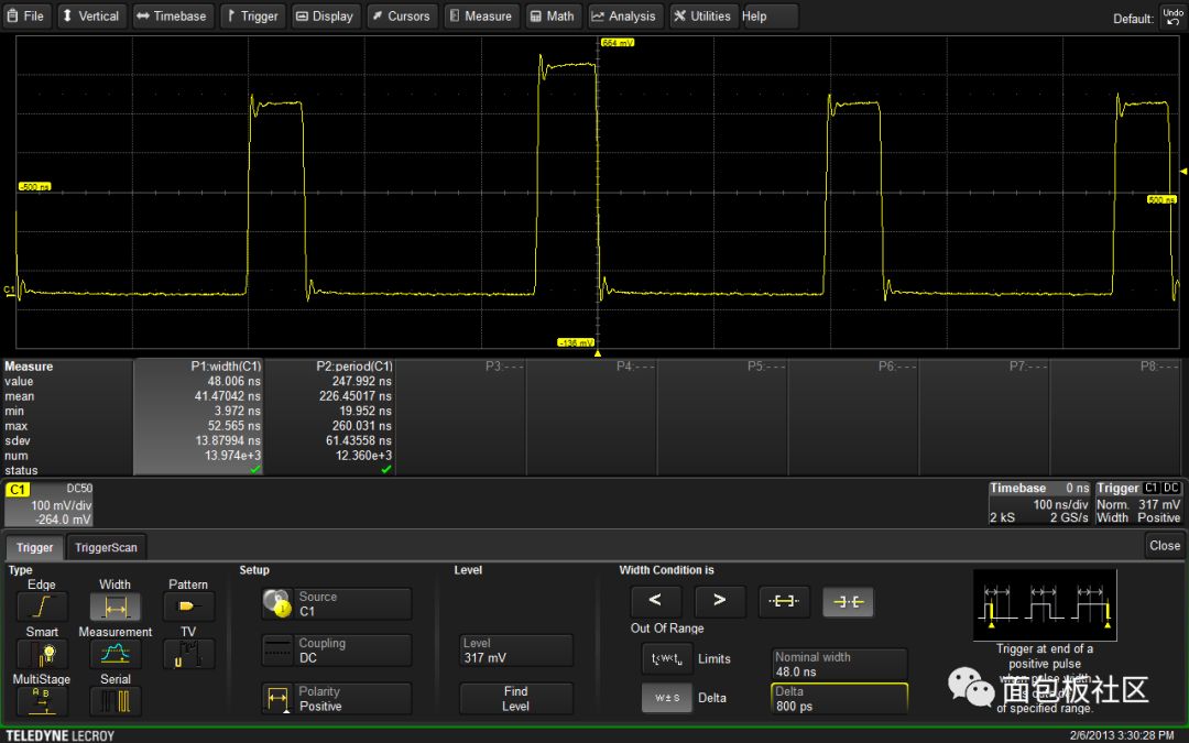
Figure 4: Width-based exclusion triggering can be used to find abnormal pulses in the clock signal. The oscilloscope triggers when the pulse width is not the nominal 48 ns.
The Width parameter is used to determine the average width of the clock signal, which in this case is 48 ns. You can use this value as the basis for the exclusion trigger. The condition for using the width trigger is that the width is outside the range of ±800ps of the nominal 48ns, that is, only the pulse with the nominal value of at least 800ps will trigger the oscilloscope.
Trigger after acquisition
Many oscilloscopes provide special triggering functions that work after acquisition, including digital or software-assisted triggering, area triggering, and measurement triggering. This type of trigger uses an auto-trigger to acquire a trace and after acquisition acquires the data to find the desired trigger condition. If a trigger condition is found, move the trace display to place the trigger event at the oscilloscope trigger indicator.
Measurement trigger
The measurement trigger triggers the oscilloscope based on the measurement result. Any measurement parameter of the oscilloscope can be used, including measurement conditions such as "less than", "greater than", "in range", "out of range", or "don't care" to trigger a specific measurement value. The oscilloscope first collects data. If a measurement condition is found, the measurement position will move to the trigger indication point. FIG. 5 is an example of a measurement trigger based on width measurement.
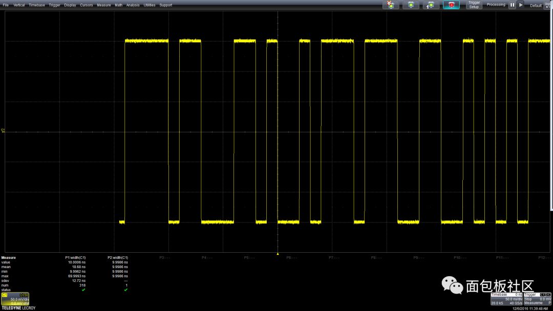
Figure 5: The measurement trigger system scans the acquired waveform and examines each measurement instance. When a user-defined condition is found, the oscilloscope aligns the event that occurred with the trigger point.
In this example, the trigger condition is a positive pulse width of 10 ns. If the acquired waveform contains a pulse of this width, the oscilloscope aligns the trigger point with the end of the pulse.
Software assisted triggering
Software-assisted triggering is used to find the trigger level crossing closest to the hardware trigger point, and then adjusts the time offset of the waveform to align with the specified trigger level and slope. The software trigger provides trigger point time gating in which to search for threshold crossings. It also allows you to manually set software-triggered hysteresis.
Multi-level or conditional trigger
Multi-level triggering involves two or more trigger sources. The setting of the event is exactly the same as the basic trigger (edge, width, mode, etc.), but one or more trigger events are used to arm the oscilloscope and triggered by the final trigger source.
The earliest multi-channel trigger function was a conditional trigger that used two events. This trigger causes the oscilloscope to be armed when event A occurs, triggering the source to trigger when event B arrives. It resets automatically after event B in normal trigger mode. Event A can be an edge, a state, a logic pattern, or a pattern state (a pattern that persists for a user-defined number of events or time). The options for the B event depend on the type of event A. Event A can only be an edge if event A is in numeric mode or mode state.
Triggering on qualifying conditions is useful when troubleshooting ICs on the bus. The signal on the IC can only be viewed after it is turned on. The trigger system is armed by chip selection and then triggered by the desired bus signal.
Cascaded triggers are more complex triggers based on multiple events that cause the trigger system to be armed when a single initial ("A") event or consecutive multiple events (up to three) occur, then trigger the oscilloscope under specified conditions. It provides trigger isolation and reset functions for each set of events to further confirm that the trigger event satisfies the trigger conditions. Figure 6 is a composite screen image showing a typical cascaded triggering system and the settings for each stage.
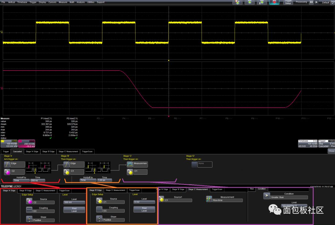
Figure 6: Composite screen image showing the cascaded cascade trigger settings. After C2 experiences a positive edge above 0.5V, the oscilloscope is in place. Triggering occurs when the positive edge of C1 crosses 0V and the rise time is greater than 325ps.
Referring to Figure 6, the oscilloscope triggers the in-position when the positive edge on channel 2 exceeds 0.5V (event A), followed by 200ns isolation, followed by the positive edge on channel 1 that exceeds 0V (event B). Satisfying these two in-position conditions, the oscilloscope will trigger when the rise time exceeds 325ps (Event C).
In FIG. 6, the parameter P1 measures the rise time of multiple acquisitions completed over the entire capture window. The P2 gates the rise time measurement so that only the value associated with the trigger point is displayed. The value of P2 is the rise time when the trigger occurs. The range of all rise times is usually 300ps to 344ps. The measured rise time corresponding to the trigger is 326ps.
Cascaded triggers can use measurements, logic patterns, or smart triggers as events in the trigger qualification chain. This is a very flexible trigger tool.
Trigger bandwidth
The oscilloscope's signal path and trigger path are usually different, so that the edge-triggered bandwidth (usually lower) is different from the signal path bandwidth. Smart triggering bandwidth is usually much lower than edge-triggered bandwidth. The manufacturer's data sheet shows the trigger bandwidth for both trigger modes.
in conclusion
Modern DSO offers a variety of trigger types and functions, including simple edge triggers, complex smart triggers, and enhanced triggers. Understanding these triggered features and applications ensures that the first time you capture the desired signal, speeds up the acquisition of measurement results and improves test throughput.
According to the needs of different office environments, office projectors are roughly divided into three categories.
One is a conventional projector that is placed or hoisted in the conference room, the second is a Portable Projector that can be carried around, and the third is an ultra-short-throw projector for convenient work reports and speeches.
With the advent of the Internet era, the emergence of wireless office series represented by ViewSonic PJD6352, PJD6550LW, PJD6252L, and PJD6552LWS has added new members to the office projectors. The wireless Office Projector is realized by the built-in wireless module of the ordinary office projector. Wireless office enables people not to switch signal lines frequently during office meetings, allowing people to have a better experience in meetings.
4k meeting room projector,video projector for meeting room,good projector for meeting room,conference room led projector,lcd meeting room projector
Shenzhen Happybate Trading Co.,LTD , https://www.szhappybateprojectors.com