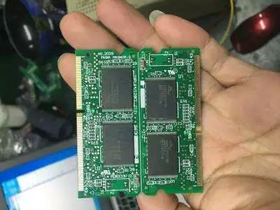
For pcb copy board, a little carelessness may cause the bottom board to be deformed. If it does not improve, it will affect the quality and performance of the pcb copy board. If it is discarded directly, it will cause a cost loss. Here are a few ways to modify the bottom board deformation correction method.

First, the splicing method
For graphics with simple lines, large line width and spacing, and irregular deformation, cut the deformed part of the film and re-stitch the holes of the control drilling test board, and then copy it again. Of course, this is for deformed lines. Simple, line width and spacing larger, irregular deformation of the graphics; for high density wire, line width and spacing less than 0.2mm not suitable for the film. When cutting, care should be taken to minimize the damage to the leads and not to damage the pads. When splicing and copying, it is necessary to pay attention to the correctness of the connection relationship. This method is suitable for the film that is not dense for the line, and the deformation of the film is inconsistent in each layer, and the correction of the solder resist film and the multilayer film power source substrate film is particularly effective.
Second, PCB copy board change hole method
Under the condition of mastering the operation technology of digital programming instrument, firstly compare the negative film with the drilling test board, measure and record the length and width of the drilling test board, and then on the digital programmer, according to its length and width. The amount of deformation, adjust the hole position, adjust the drill plate to meet the deformation of the film. The advantage of this method is that it eliminates the tedious work of splicing negatives and guarantees the integrity and accuracy of the graphics. The inadequacies are: the correction of the local deformation is very serious, uneven deformation of the film, the effect is not good. To use this method, you must first master the operation of the digitizer. After using the programmer to lengthen or shorten the hole position, reset the poor hole position to ensure accuracy. This method is suitable for the correction of line-constrained film, or the deformation of the film in each layer.

Third, the pad overlap method
The holes on the test board are magnified into pads to deform the overlapping circuit boards to ensure the minimum ring width requirement. Due to the overlapped copy, the pad is elliptical, and after the overlapped copy, the halo and deformation of the line and the plate edge. If users have very strict requirements on the appearance of the PCB, please use it with caution. This method is suitable for film with a line width and spacing of more than 0.30mm and less graphic lines.
Four, photo method
Just use the camera to enlarge or reduce the deformed image. Normally, the loss of the film is high, and it takes a lot of debugging to obtain a satisfactory circuit pattern. Focus accurately when photographing to prevent line distortion. This method is only suitable for silver salt film, in the inconvenience to re-drill test board, and the film length and width direction of deformation of the same ratio can be used.
Fifth, hanging hanging method
For the physical phenomenon that the film changes with the temperature and humidity of the environment, remove it from the sealed bag before copying the film, and let it hang in the working environment for 4 to 8 hours so that the film is deformed before copying. After copying, the chance of deformation is very small.
For the already deformed film, you need to take other measures. Because the film will change with changes in the temperature and humidity of the environment, when hanging the film, it is necessary to ensure that the humidity and temperature at the hanging area and the work area are the same, and it is necessary to ventilate it in a dark environment to avoid contamination of the film. This method is suitable for a film that has not yet been deformed, and it can also prevent the film from being deformed after copying.
1.25mm Wire To Board Connectors
1.25mm Wire To Board Connectors are avialable in different terminations and sizes intended for use on a variety of applications. These connectors provide power and signal with different body styles, termination options, and centerlines. To find the wire to board set required, click on the appropriate sub section below.
Description
1.25mm wire-to-board connector system is designed for a wide variety of applications in Industrial, Automotive, and Consumer markets.
The comprehensive range consists of terminals, crimp housings and PCB headers in straight and right angle, surface mount and through-hole configurations. It is available in 2 to 15 circuits in a single row. 1.25mm wire-to-board solution conforms to the EU Industry Safety Standard. PCB header material meets halogen-free requirements and can be operated in the temperature range from -40°C to +105°C.
Saves space with a 1.25mm pitch
Suitable for Industrial, Automotive, and Consumer markets
Crimp housing with friction feature
Conforms to EU Industry Safety Standard
Accommodates wire range up to 32AWG-28AWG
Features
Three plating versions - Tin 15μin Gold, 30μin Gold and Gold Flash
Fully polarized housings
Crimp housing with friction feature
Tape and Reel packaging with pick up cap
UL94V-0 flammability rated LCP material
Halogen-free resin material
RoHS compliant and lead-free
Benefits
Supports applications in a wide range of environments
Prevents accidental mismating
Provides additional retention and prevents harness-to-header mismating
Pick and place for SMT production process
High flammability rating
Meets environmental requirement
Meets environmental, health and safety requirement
Applications
Consumers
Car Audio
Industrial & Instrumentation
Industry Control
Instrumentation/Metering
Office Equipment
Small Motor/Robot Control
Security
Alarm Systems
Vending POS Machine
Automotive Connector,1.25Mm Wire To Board Connectors,1.25Mm Pcb Wire To Board Connector,1.25Mm Pin Wire To Board Connector,.049" Pitch Wire To Board Connectors
ShenZhen Antenk Electronics Co,Ltd , https://www.antenkcon.com
![<?echo $_SERVER['SERVER_NAME'];?>](/template/twentyseventeen/skin/images/header.jpg)