![<?echo $_SERVER['SERVER_NAME'];?>](/template/twentyseventeen/skin/images/header.jpg)
☆What is the difference between the mathematical operation instruction in the PLC ladder diagram and the mathematical operation instruction in the statement table?
In Siemens S7-200 series PLCs, the mathematical operation instructions of the ladder diagram are represented by boxes, and the mathematical operation instructions in the statement table are represented by mnemonics. The two forms of expression are different, and the mnemonics may also have large differences.
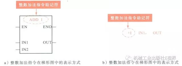
Fig.: Mnemonic instruction in ladder diagrams and statement tables for math operation instructions
In addition, the function and use of mathematics instructions in ladder diagrams and statement tables are also different. In the ladder diagram, the operation performed by the addition instruction of integers, double integers, and real numbers is
IN1+IN2=OUT
In the statement table, the operation performed by the add instruction is
IN1+OUT=OUT
The result of the addition instruction in the ladder diagram is the sum of the two inputs; the addition instruction in the statement table is the sum of the input and output quantities, and these differences should be noted in the design of the program.
☆ How do two PLCs establish communication?
Two S7-200 series PLCs establish communication. First, the PORT0 ports of the two PLCs are connected through a communication cable, and PPI communication is implemented through the PPI protocol (Point-to-Point Interface Protocol).
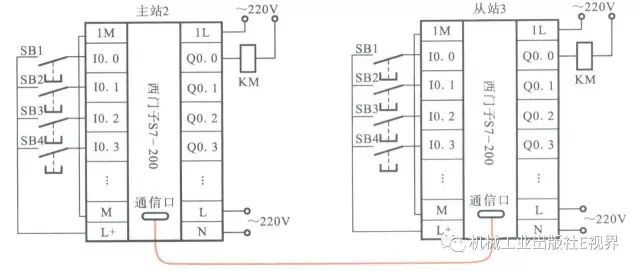
Figure: Connection between two S7-200 series PLCs
According to the communication instruction mode, first establish the PPI master mode (set SMB30/SMB130 communication port), and analyze the communication process according to the TBL data table (status byte, remote device address, data pointer, data length, etc.).
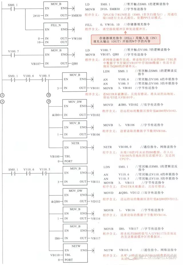
Figure: Communication program for two S7-200 PLCs
What is the difference between SM0.1 and SM0.3 in PLC?
In Siemens S7-200 series PLCs, SM0.1 and SM0.3 are closed only for one scan cycle when the PLC goes from STOP to RUN. The difference between the two special flags memory is that SM0.1 closes one scan cycle when the PLC is energized to enter RUN mode and the mode switch is used to switch the PLC from STOP simulation to RUN mode; SM0.3 is closed only when the PLC is energized and enters RUN mode. A cycle.
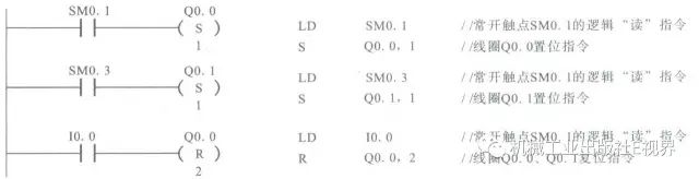
Chart: The difference between SM0.1 and SM0.3 in the Siemens S7-200 series PLC
In the figure above, both Q0.0 and Q0.1 are powered when the PLC is powered on. If the mode switch is used to switch the PLC from STOP mode to RUN mode while the PLC is powered on, only Q0.0 is energized.
☆ PLC control motor brake statement statement how to write?
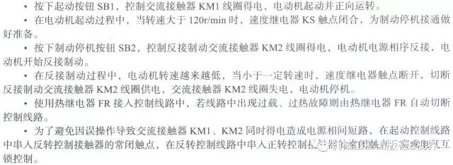
1. Control requirements
2. Partition the control relationship and allocate the I/O allocation table of the PLC statement table
According to the requirements of reverse braking control, the control functions are first decomposed and divided into two modules: starting and braking according to their functions.
According to the above control requirements, the input device mainly includes a start button SB1, a brake button SB2, a thermal relay thermal element FR, and a speed relay contact. Therefore, there should be 4 input signals.
The output device mainly includes two AC contactors, namely the control motor M starts the AC contactor KM1 and the AC contactor KM2 that reverses the braking. Therefore, there should be two output signals.
Correspond to the input device and output device element number and Mitsubishi PLC statement statement operands (programming element address number) to correspond, fill in the Siemens PLC statement table I / O allocation table.
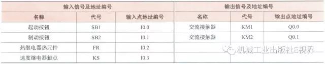
Fig.: I/O assignment table of SIEMENS PLC statement table for motor reversal brake control
3. Programming
After dividing the motor reversal brake control module and drawing the I/O allocation table, the statement table can be written according to the control requirements of each module. Finally, the statement tables of each module are combined.
(1) Programming of statement tables for motor starting control modules
Control requirements: press the start button SB1, control AC contactor KM1 energized, motor M start running, and when the start button SB1 release, still maintain continuous operation; press the reverse brake button SB2, AC contactor KM1 missing Electricity, motor failure; AC contactors KM1, KM2 can not be at the same time.

Fig.: Programming of statement tables for motor starting control modules
(2) Programming of statement table of motor reversal brake control module
Control requirements: press reverse brake button SB2, AC contactor KM2 get power, KM1 loses power, and after releasing SB2, still maintain KM2 get power; and require the motor to reach a certain speed, it is possible to achieve reverse braking control. In addition, AC contactors KM1, KM2 cannot be powered at the same time.

Fig.: Programming of the statement table of the motor reversing brake module
Combining the statement tables of the two modules, and finishing the statement table program of the motor reverse brake PLC control.
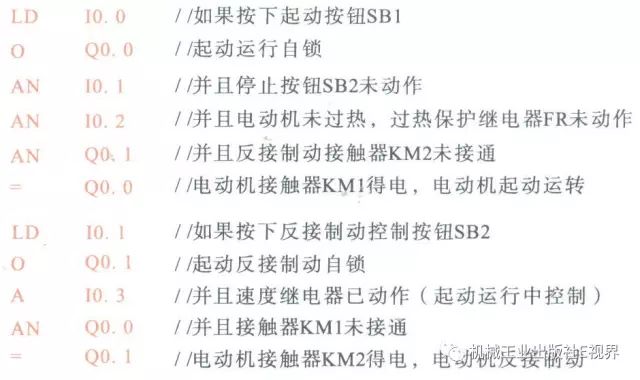
Figure: The statement table program for the reversed connection of the brake PLC to the motor obtained by the final combination
4. Special tips
Because the statement table programming is directly abstracted by using instructions directly, in most cases, the statement table is usually used together with the ladder diagram language, that is, the ladder diagram program is written first, and then the conversion is performed one by one according to the application rule of the programming instruction.
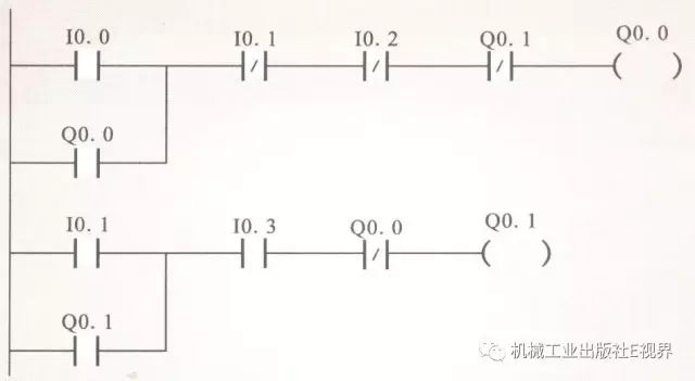
Fig.: Ladder program for motor reversal brake PLC control
According to the application rules of each programming instruction, the ladder diagram is directly converted into a statement table. Basic principle: Write one by one according to the ladder diagram from top to bottom and from left to right.
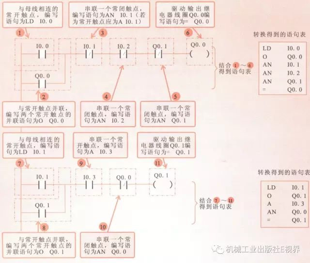
Figure: The conversion method of the Simon PLC ladder diagram to the statement table
In addition, most of the programming software can automatically convert the ladder diagram and the statement table, so you can draw a good ladder diagram in the programming software, and then through the software "ladder diagram / statement table" conversion.

Figure: Using Programming Software to Convert Ladder Diagrams and Statement Lists
It is worth noting that in the programming software, ladder diagrams and statement tables can be converted to each other. Basically all the ladder diagrams can be directly converted to the corresponding instruction statement table; but the instruction statement table may not all be directly converted to the corresponding ladder diagram, and it needs to pay attention to the corresponding format and the use of instructions.
☆ PLC control motor continuous statement statement how to write?
After the above detailed introduction, Xiao Bian will simplify this paragraph. If you have any questions, you can leave a message.
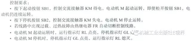
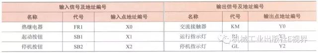
Figure: Mitsubishi PLC statement table I/O allocation table for continuous motor control
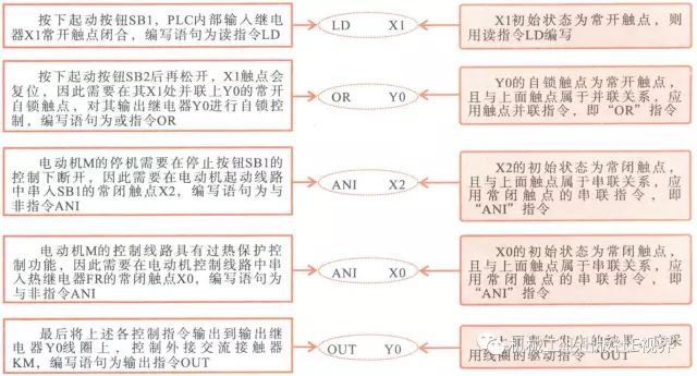
Fig.: Programming of the start statement of the motor M start control block

Fig.: Programming of the run statement RL control module statement table
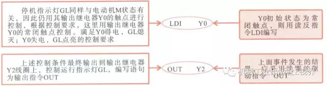
Fig.: Programming of shutdown statement GL control module statement table
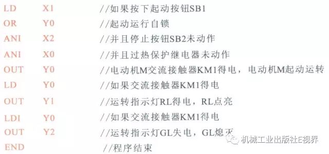
Fig.: The completed motor continuous control statement table program
☆ PLC control two motor sequential statement statement how to write?

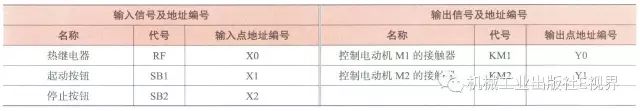
Figure: I/O address allocation table of Mitsubishi PLC statement table for motor sequential start control
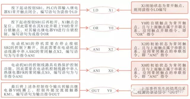
Fig.: Programming of statement tables for start and stop control modules for motor M1
Figure: Programming of the statement control table of the time control module
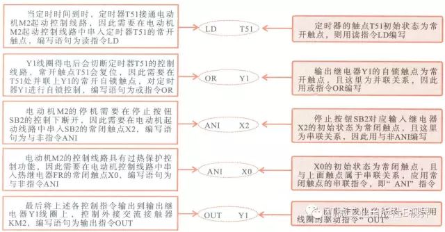
Fig.: Programming of statement tables for motor M2 start and stop control modules
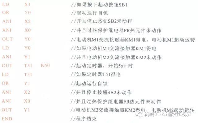
Figure: Completed motor sequential start control statement statement program
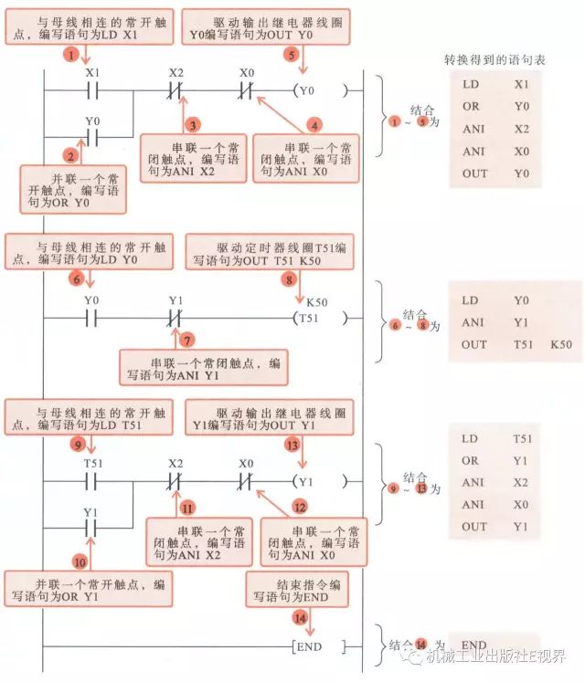
Figure: Conversion of Ladder Diagram Program and Statement List Program for PLC Control of Motor Sequence Startup
Gold Room Switch And Socket,Gold Double Light Switch,Gold Homekit Light Switch,Dimmer Switch
ZHEJIANG HUAYAN ELECTRIC CO.,LTD , https://www.huayanelectric.com