![<?echo $_SERVER['SERVER_NAME'];?>](/template/twentyseventeen/skin/images/header.jpg)
In recent years, the defective Microstrip Structure (DMS, formerly referred to as EBG) has attracted the attention of experts and scholars both at home and abroad due to its advantages of high impedance bandwidth and small size. It directly etched high-inductance microstrip lines. High capacitance, so it is easy to process. The low-pass filter designed by using its high-inductance, high-capacitance, low-pass band-stop characteristics can be used for harmonic suppression of microwave active devices such as power amplifiers [1] and mixers [2, 3].
In the L and S bands, experts and scholars at home and abroad have done a lot of research work on DMS structures on low-dielectric constant substrate materials, and there are relatively few reports on high-frequency substrates and high dielectric constant substrates. In order to realize the wide resistance band and small size characteristics of DMS applied to high frequency band and high dielectric constant materials, it is necessary to make a new discussion on it.
1, DMS structural characteristics
Figure 1, DMS structure T-shaped unit
The DMS structural unit is shown in Fig. 1. The microstrip medium consists of three layers of Ferro-A6M green tape. The thickness of each green tape sintered is 0.096mm, and the thickness of three layers is 0.288mm. The relative permittivity of the material is εr=5.9. Tangent tan δ = 0.0015. The 50Ω microstrip line width at both ends is 0.43mm. The low-impedance microstrip line at the DMS is used to compensate for the DMS high-impedance characteristics to achieve a 50Ω matching impedance of the filter. The low impedance compensation segment uses a 34Ω microstrip line width of 0.82mm. Using HFSS (High Frequency Simulator Simulator) simulation analysis, T-shaped unit "a horizontal" gap width has little effect on transmission performance, we change the length of the T-shaped unit "a horizontal" gap, from the simulation analysis of Figure 2, DMS The T-shaped unit has a band-stop low-pass characteristic, and the resonant frequency decreases as the T-shaped "a transverse" gap length increases. The resonant frequency decreases as the length of the T-shaped “vertical†increases, as shown in Figure 3. Figure 4 shows that the "vertical" width of the T-shape increases and the resonant frequency increases.
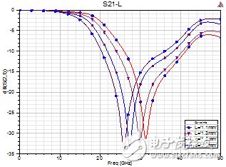
Figure 2. Characteristics of the transmission coefficient of a TMS T-cell as a function of the "L" length L
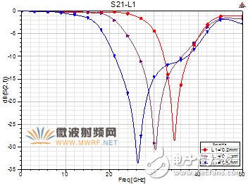
Figure 3: Characteristics of the transmission coefficient of a DMS T-cell as a function of "vertical" length L1
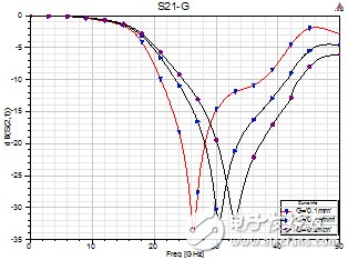
Fig. 4. Characteristics of the transmission coefficient of a DMS T-cell as a function of the "vertical" width G
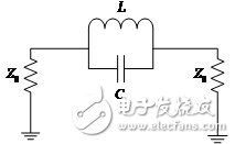
Figure 5, DMS structure T-cell LC equivalent circuit
It can be seen from the simulation results that the T-shaped unit has low-passband resistance and single-pole resonance characteristics. The related literature[4-7] has done valuable work on its equivalent circuit. A single T-shaped unit can be equivalent to L. The C-band band-elimination filter can be extracted from the transmission coefficient S21 obtained from the previous EM electromagnetic simulation:
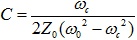 (1)
(1)
 (2)
(2)
Where ωc is the 3dB cutoff frequency, ω0 is the resonant frequency, and Z0 is the characteristic impedance of the filter.
L, C is extracted by equation (1)(2), and the equivalent circuit transmission coefficient is obtained by analysis in ADS software. Figure 6 shows the comparison of the transmission coefficient of single T-cell electromagnetic simulation and equivalent circuit analysis. It can be seen that The equivalent overall amplitude-frequency response agrees well with the electromagnetic simulation results.
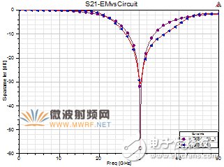
Figure 6, EM simulation and equivalent circuit transmission coefficient (circle for circuit S21)
The equivalent model also explains the change characteristics of Figure 2 to Figure 4 in a physical sense. The main characteristic of the thin wire above the “one horizontal†slot of the T-shaped cell is the inductance L, T-shaped element in the equivalent circuit. The main characteristic of the "vertical" gap performance is the capacitance C in the equivalent circuit. As the length of the T-shaped unit increases, the inductance value L increases, and the resonant frequency decreases. The length of the T-shaped unit's “vertical†gap increases, which corresponds to an increase in the capacitance C in the equivalent circuit, which also leads to a decrease in the resonant frequency. As the width of the "vertical" slit of the T-shaped unit increases, the capacitance value decreases and the resonant frequency increases.
2. DMS low-pass filter designIn order to expand the stopband width, two T-shaped units are cascaded in FIG. 7, and the scattering parameters as shown in FIG. 8 are obtained by adjusting the structural parameters of a single T-shaped unit and the distance between them. It can be seen from the simulation curve that the passband insertion loss is 0.2dB, the return loss is greater than 19dB, and the second harmonic of the local oscillator is suppressed by 20dB at 19.6GHz, and the frequency range of suppression is greater than 30dB is 22GHz-30GHz.
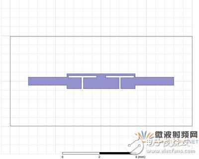
Figure 7. Two DMS T-cell cascades
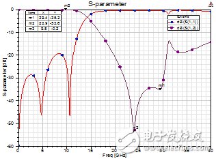
Figure 8. Two DMS T-cell scattering parameters
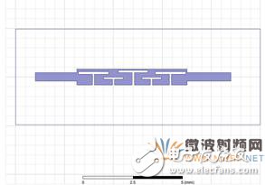
Figure 9, five DMS T-shaped units LPF

Figure 10, HL HL impedance line LPF layout
In order to further increase the stopband suppression and stopband bandwidth, the T-shaped unit was increased to five LPFs (Low Pass Filter), the structure is shown in Figure 9, and the stopband was increased by 6GHz through parameter optimization. The results are shown in Figure 10. For the second local oscillator frequency, the third local oscillator frequency and the mixed harmonic clutter from 20 GHz to 36 GHz achieve a suppression of 30 dB, the passband insertion loss is 0.3 dB, the return loss is greater than 19 dB, and the size is only 5.7 mm & TImes; 1.7 mm.
At the same time, in order to illustrate the performance and size of the filter, we designed a 7th order Chebyshev high and low impedance line low-pass filter in the circuit, as shown in Figure 10, its size is 8.4mm & TImes; 3.4mm, its performance parameters As shown in FIG. 11 , it can be seen that the DMS low-pass filter has a high volume and a low-impedance LPF is reduced by 66%, and more than 30 dB suppresses the increase in the stop-band bandwidth by about 5 GHz.
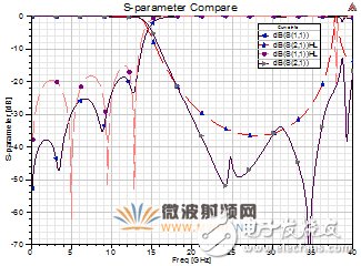
Figure 11. Comparison of LPF performance between DMS TLP LPF and HL High and Low (HL) Impedance LPF
3, the conclusionStarting from the simple T-shaped DMS unit, its physical qualitative interpretation and the influence of the dimensional change on the frequency response are given. Finally, based on the LTCC substrate, a low-pass filter with a cut-off frequency of 13 GHz was designed by gradually adding a T-shaped unit. Compared with the high- and low-impedance lines LPF, the volume is reduced by 66% and the stop band is increased by 5 GHz.
Wuxi Lerin New Energy Technology Co.,Ltd. , https://www.lerin-tech.com